Fuel vapor processors

a technology of fuel vapor and processor, which is applied in the direction of combustion air/fuel air treatment, separation processes, machines/engines, etc., can solve the problems of reducing the opportunity for removing the fuel vapor trapped in the canister, not being able to utilize negative pressure in the air intake pipe during stopping, and reducing so as to increase the treatment capacity and improve the recovery amount of fuel vapor , the effect of increasing the desorption efficiency

Active Publication Date: 2012-09-25
AISAN IND CO LTD
View PDF14 Cites 22 Cited by
  • Summary
  • Abstract
  • Description
  • Claims
  • Application Information

AI Technical Summary

Benefits of technology

[0017]In accordance with this aspect, during desorption of the fuel vapor, fresh air is led into the canister via the pressure regulator while keeping negative pressure in the canister, so that it is able to ensure gas flow and to increase desorption efficiency. Thus, recovery amount of the fuel vapor is improved and the adsorbent in the canister can be renewed well, so that treating capacity can be increased.

Problems solved by technology

For example, “idling stop system” stops the engine during stopping at a red light or the like, so that it is not able to utilize negative pressure in the air intake pipe during stopping.
Whereas, “hybrid system” stops the engine during drive mode by an electric motor, so that it is not able to utilize negative pressure in the air intake pipe during such drive mode.
Thus, opportunities for removing the fuel vapor trapped in the canister decrease, so that the adsorbent in the canister cannot be renewed adequately.
Therefore, it is difficult to appropriately treat the fuel vapor.
In addition, some of vehicles equipped with “direct injection fuel engine” for directly injecting fuel into a combustion chamber do not have any throttle valve, so that it is difficult for this type vehicle to purge the fuel vapor trapped in the canister into the air intake pipe.
The fuel vapor processor disclosed in Japanese Laid-Open Patent Publication No. 10-259765 utilizes negative pressure in the air intake pipe, so that it would be difficult to mount the processor on a vehicle having “idling stop system” or “hybrid system”.
However, when the inner pressure of the canister reaches a limit for pressure reduction, gas hardly flows in the canister, so that fuel vapor cannot be removed any more.
Therefore, desorption efficiency (desorption amount) is not enough.
However, a suction device such as vacuum pump is not provided, so that when the inner pressure of the fuel tank reaches allowable lower limit for negative pressure, back-purge takes place.
Thus, the number of members required for power distribution increases, so that the numbers of members such as distributing cable and assembly steps increase, and consumed power and loss during power transmission also increase.
In addition, separation efficiency by the separation membrane is not 100%, so that diluted gas separated by the separation membrane would include components of fuel.

Method used


Image

  • Fuel vapor processors
  • Fuel vapor processors
  • Fuel vapor processors

Examples


second embodiment

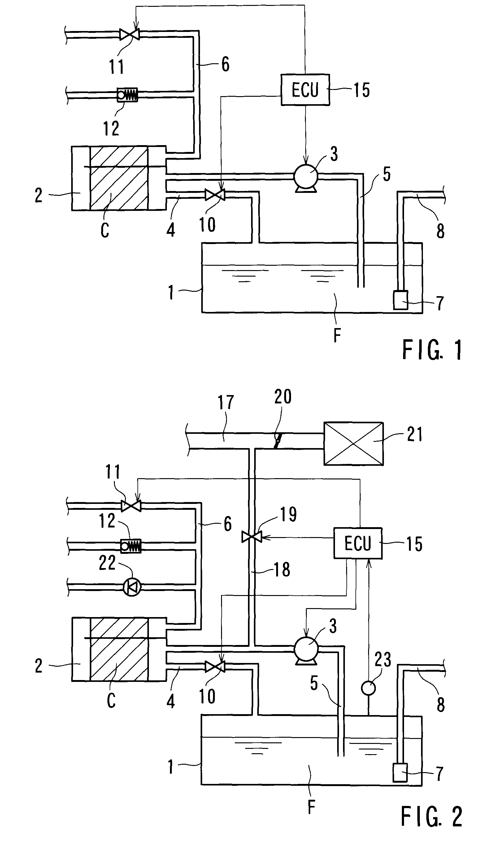
[0059]As shown in FIG. 2, the recovery pipe 5 is communicated with an air intake pipe 17 via a purge pipe 18 between the canister 2 and the vacuum pump 3 in the The purge pipe 18 is provided with a purge pipe valve 19 for switching an open state and a closed state of the purge pipe 18. The purge pipe valve 19 is composed of a solenoid valve controlled by the ECU 15. The air intake pipe 17 is provided with a throttle valve 20 for controlling an amount of air intake, and is connected with an air cleaner 21. In addition, the air pipe 6 between the air pipe valve 11 and the canister 2 is communicated with a pipe equipped with a one-way valve 22, which allows gas flow from the canister 2 toward the outer space. Further, the fuel tank 1 is provided with a pressure sensor 23 for detecting inner pressure of the fuel tank 1. The pressure sensor 23 is one example of the inner pressure detector. The inner pressure detected by the pressure sensor 23 is translated into signals, and then the sig...

first embodiment

[0060]In a state that the ignition switch or the like is off, the vapor pipe valve 10 is open, whereas the air pipe valve 11 and the purge pipe valve 19 are closed. When the fuel vaporizes in the fuel tank 1 in this state, the fuel vapor is led into the canister 2 via the vapor pipe valve 10 like the first embodiment, however air passing through the canister 2 is released into the atmosphere via the one-way valve 22. When the ignition switch or the like is turned on, the air pipe valve 11 and the purge pipe valve 19 are opened. In addition, when the engine is driven, air is led to the engine from the air cleaner 21 while controlling flow rate of air in the air intake pipe 17 due to the throttle valve 20. Then, negative pressure in the air intake pipe 17 acts on the purge pipe 18, so that the fuel vapor is removed from the canister 2 due to the negative pressure and is delivered into the engine through the purge pipe 18 and the air intake pipe 17. In this state, the air pipe valve 11...

fifth embodiment

[0077]In addition, in the fifth embodiment, the second pressure regulation valve 40 can be disposed on the second circulation pipe 52. In this case, pressurized force due to the pressure pump 34 acts on the receiving chamber 50 for the third separation membrane 48 in addition to the receiving chamber 27 for the first separation membrane 25 and the receiving chamber 31 for the second separation membrane 29, so that separation efficiency by the third separation membrane 48 is further increased.

[0078]A sixth embodiment has a pressure swing adsorption device in addition to the basic configuration of the first embodiment. In particular, as shown in FIG. 10, a four-way valve 55 is disposed on the recovery pipe 5, and the pressure swing adsorption device (PSA) 56 is communicated with the four-way valve 55. The PSA 56 is two-tower type PSA having a first adsorption tower 56a and a second adsorption tower 56b parallel to each other such that when one of the adsorption towers adsorbs the fuel...


PUM

PropertyMeasurementUnit
atmospheric pressureaaaaaaaaaa
negative pressureaaaaaaaaaa

Abstract

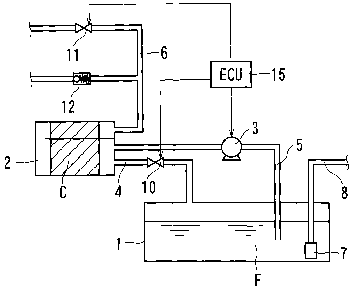
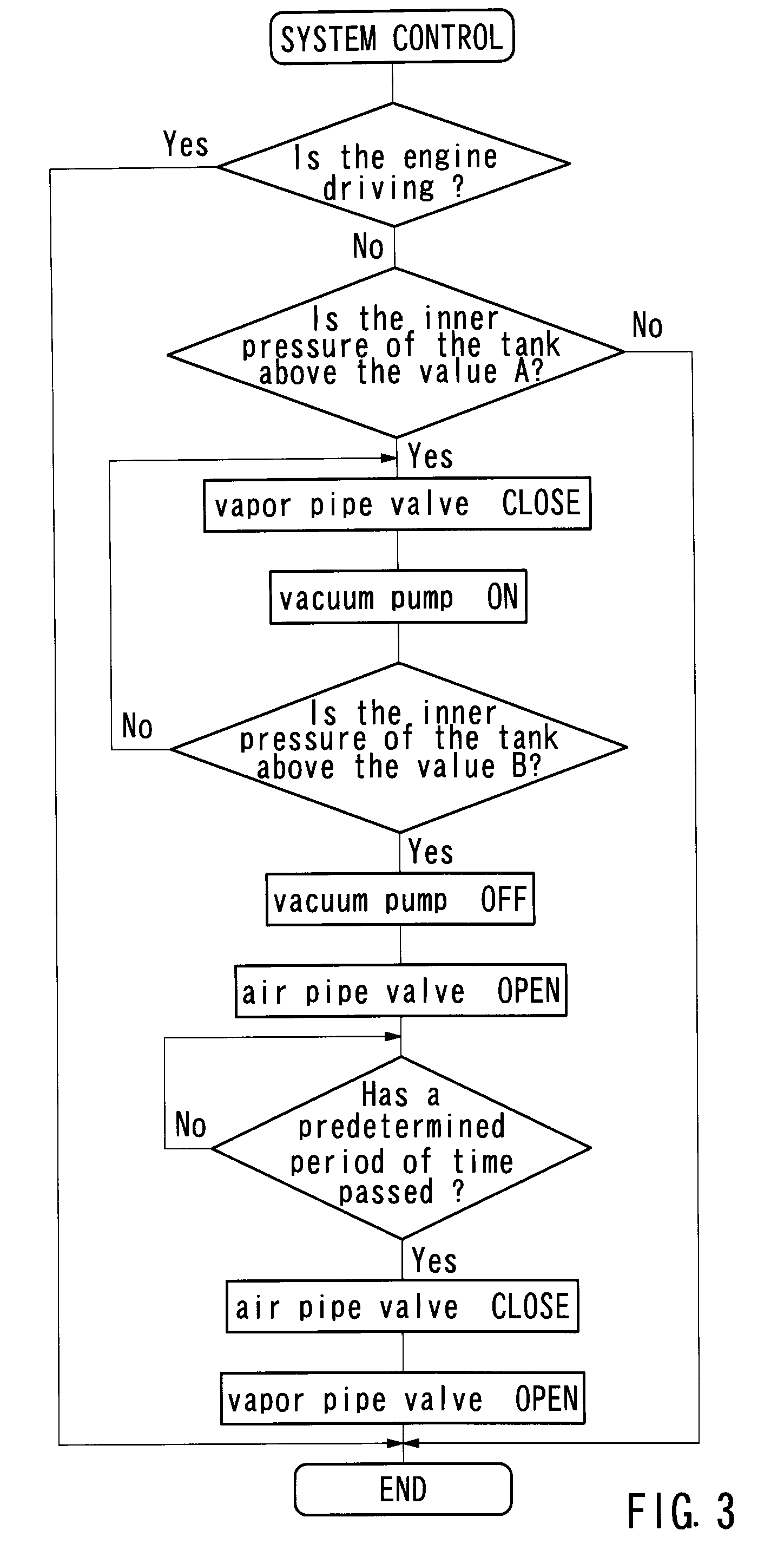
A fuel vapor processor has a fuel tank, a canister, a vapor pipe, a recovery pipe, an air pipe, a suction device, a vapor pipe valve, an air pipe valve, and a pressure regulator. The vapor pipe leads fuel vapor generated in the fuel tank to the canister for trapping the fuel vapor in the canister. The recovery pipe recoveries the fuel vapor desorbed from the canister into the fuel tank. The air pipe communicates the canister with the atmosphere. The suction device is disposed on the recovery pipe for desorbing the fuel vapor trapped in the canister. The pressure regulator is communicated with the air pipe between the air pipe valve and the canister in order to allow gas flow from the atmosphere toward the canister. During desorption of the fuel vapor due to the suction device, the vapor pipe valve and the air pipe valve are closed, and negative pressure is kept in the canister such that the fuel vapor is desorbed from the canister and fresh air is led into the canister via the pressure regulator.

Description

CROSS-REFERENCES TO RELATED APPLICATIONS[0001]This application claims priority to Japanese patent application serial number 2009-165525, the components of which are incorporated herein by reference.BACKGROUND OF THE INVENTION[0002]1. Field of the Invention[0003]The present invention relates to devices for treating fuel vapor, in particular, fuel vapor processors for trapping fuel vapor, which has vaporized in a fuel tank, in a canister and recovering the fuel vapor from the canister to the fuel tank due to a suction device.[0004]2. Description of the Related Art[0005]A gas vehicle is equipped with a fuel vapor processor for preventing fuel vapor vaporized in a fuel tank from flowing into the atmosphere for environmental protection or the like. The fuel vapor processor includes a canister filled with adsorbent and temporally traps the fuel vapor by adsorbing the fuel vapor onto the adsorbent. As for a conventional fuel vapor processor shown in Japanese Laid-Open Patent Publication No...

Claims


Application Information

Patent Timeline
Patent Type & Authority Patents(United States)
IPC IPC(8): F02M25/08B01D53/04
CPCB01D53/0415B01D53/047F02M25/0872B01D53/0476B01D2253/102B01D2256/14B01D2257/106B01D2257/702B01D2259/40007B01D2259/40056B01D2259/402B01D2259/4516B01D2259/4566B01D2259/655
Inventor MAKINO, KATSUHIKOSHINAGAWA, MASANOBUTESHIMA, HIDEKIMANI, TAKASHI
Owner AISAN IND CO LTD
Why Eureka
Try Eureka