Ultrasound treatment clamp

a clamp and ultrasound technology, applied in the field of medical instruments, can solve the problems of limiting the use of these devices, affecting the ability of the diseased part to grow, infiltration and metastasis, and the operation procedure is very complex, so as to reduce facilitate manual operation, and reduce the effect of the possibility of blood transfusion

Active Publication Date: 2012-10-09
CHONGQING HAIFU (HIFU) TECHNOLOGY CO LTD
View PDF13 Cites 135 Cited by
  • Summary
  • Abstract
  • Description
  • Claims
  • Application Information

AI Technical Summary

Benefits of technology

[0006]Aiming at the disadvantages in the prior art as mentioned above, the technical problem is solved in the present invention by providing an ultrasound treatment clamp with a compact structure, a convenient operation, a low treatment cost, a capability of quickly causing a coagulative necrosis of the diseased part to avoid excessive lose of blood of a patient, and an abroad use.
[0010]The parallel moving mechanism enables the focal regions of two ultrasound therapy applicators to be in the same straight line in any opening degree of the treatment clamp, i.e. it can keep the central axes of two applicators overlapping each other all along. Thus, when high-intensity ultrasound energy is needed for a treatment, the ultrasound energy can be accumulated, i.e. two applicators apply ultrasound energy simultaneously to the same diseased part, so the therapeutic effects can be enhanced. During treatment, the time to cause a coagulative necrosis of the thick diseased tissue (for example, the liver or spleen) by using the applicators in the present invention is greatly shorter than that by using the ultrasound applicators in the prior art, so the treatment cost is saved. Meanwhile, the ultrasonic energy is emitted from more than one ultrasound applicator, so other internal organs will not be injured.
[0020]In the present invention, before the resection of tissue having a highly vascularized constitution (for example, spleen, kidney, liver and etc.), the high-intensity focused ultrasound is applied to cause a coagulative necrosis area between the area to be resected and the area to be reserved. Therefore, during the resection of tissues such as liver, the coagulative necrosis area is taken as the area to be resected by a surgical knife. The structure of the treatment clamp in the present invention offers an easy manual operation by an operator. Through an operation of two clamps, two ultrasound therapy applicators can firmly clamp the target tissue. Thus, the target tissue can be controlled effectively. The resection will not cause excessive blood loss, so the possibility of blood transfusion is reduced and also the occurrence of complications after surgery is decreased. Moreover, the two ultrasound therapy applicators of the present invention can work simultaneously, by which the time to cause a coagulative necrosis of the incisions is shortened and the effect of the hemostasis of the target tissue is ensured.
[0021]The present invention also has other advantages such as possessing a compact structure, low treatment cost and abroad uses (the ultrasound transducer with different specifications can be chosen according to different needs).

Problems solved by technology

Therefore, it can selectively cause a coagulative necrosis of the diseased tissue and accordingly deprives the diseased part of capability of proliferation, infiltration and metastasis.
The ultrasound apparatuses disclosed by the above-mentioned US patents can, to some extent, provide a hemostasis in the resection of tissue having a highly vascularized constitution, but there are some limits on the use of these apparatuses.
Firstly, the operator needs to continuously move the large-sized ultrasound transducer by hand in the same angle according to different surgical incisions, so the operation procedure is very complex and also it is liable to cause mishandlings.
Secondly, when the tissue to be treated is soft and incompact, the pressure generated by the apparatuses as mentioned above on the target tissue is not enough, so it is impossible to control the target tissue effectively, and if the target tissue can not be controlled, the ultrasonic energy can not arrive at the target tissue and the expected hemostasis can not be achieved.
Thirdly, because the ultrasound apparatuses mentioned above can form only one focal point within the diseased part and usually the ultrasonic energy is attenuated on the acoustic path, it takes a lot of time to cause a coagulative necrosis of the relatively thick tissue (for example, the liver and spleen) during treatment and accordingly the cost is increased.

Method used


Image

  • Ultrasound treatment clamp
  • Ultrasound treatment clamp
  • Ultrasound treatment clamp

Examples


embodiment 1

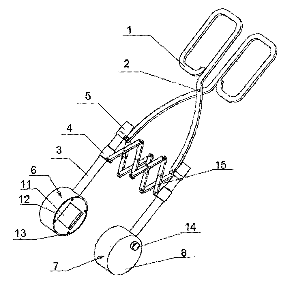
[0045]As shown in FIG. 1, the present invention comprises a handle 1, ultrasound therapy applicators and a parallel moving mechanism. Wherein, the handle 1 is clamp-shaped and two clamps of the handle 1 are connected by a pin 2. There are two ultrasound therapy applicators, which respectively are a first therapy applicator 6 and a second therapy applicator 7 mounted respectively face to face on two front ends of the clamp-shaped handle 1 and the central axes of the two applicators overlap each other.

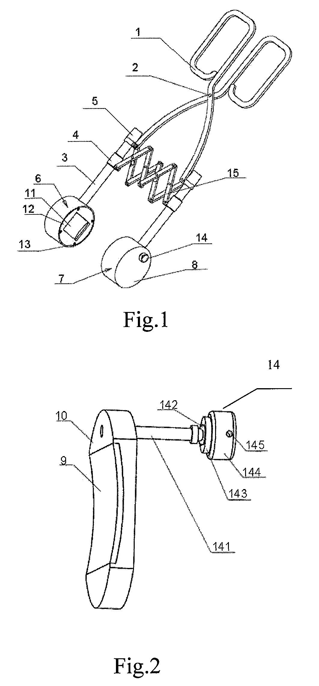
[0046]Each of the first therapy applicator 6 and the second therapy applicator 7 comprises a fluid container 8, an ultrasound transducer 9, an acoustic transparent membrane 11, a cover board 12 and a connection tube 3. The connection tube 3 is connected to the ultrasound transducer 9 at one end and is connected to the clamp of the handle 1 at the other end. The ultrasound transducer 9 is placed in the fluid container 8. The acoustic transparent membrane 11 is fixed on the open part of th...

embodiment 2

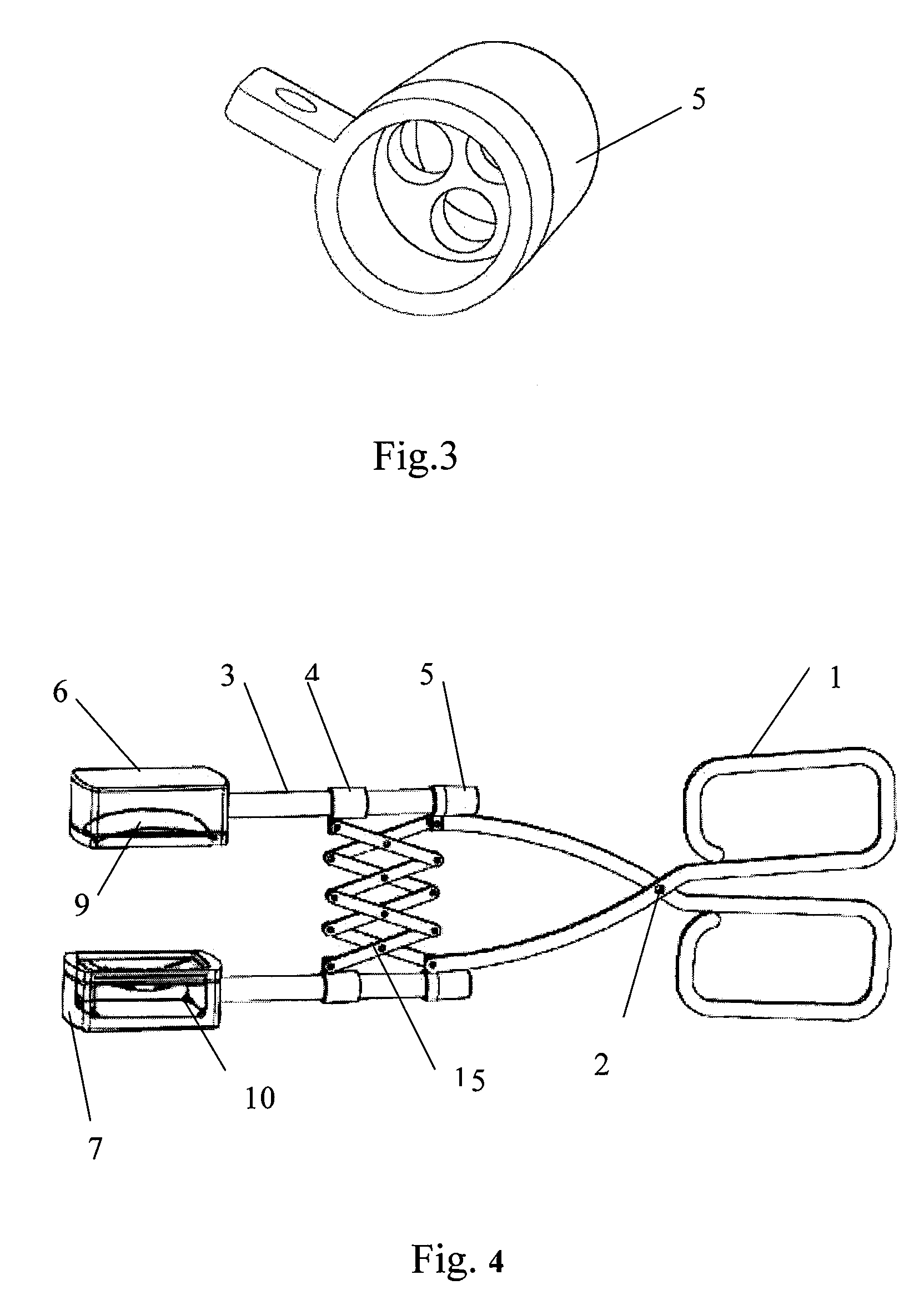
[0058]As shown in FIG. 4, the main differences between the present embodiment and the embodiment 1 are as follows: the ultrasound transducers in the present embodiment adopt focusing single arc surface piezoelectric ceramic crystals. This kind of ultrasound transducers is mainly used for hemostasis during surgery and treating the deep-bedded and big-sized diseased parts. Meanwhile, in this embodiment, the two ultrasound therapy applicators have no focal distance adjusting device 14 provided thereon, therefore, the shape of the bracket 10 of the ultrasound transducer 9 is different from that in the embodiment 1. In this embodiment, there is a support leg on the bracket 10 and the support leg is fixed in the ultrasound therapy applicator to make the bracket more firm and steady.

[0059]The other structures and the using methods of the present embodiment are the same as those in the embodiment 1.

embodiment 3

[0060]As shown in FIG. 5, in this embodiment, slots 16 are provided in the two ultrasound transducers 9. The semiconductor lighting device 17 are fixed in the slots 16 through bonding for guiding the ultrasound transducer 9 to perform a precise treatment. Before treatment, according to the position of light beams emitted from the semiconductor lighting device 17, the operator can locate the ultrasound applicator on the surface of the target tissue, and the intersection point of the focusing area of the therapy applicator and the position of light beams of the semiconductor lighting device 17 is confirmed so that a precise treatment can be performed.

[0061]In this embodiment, the ultrasound transducer 9 adopts a piezoelectric ceramic crystal array comprising of multiple piezoelectric ceramic crystals with the same size or different sizes. The driving mode of this array is a multi-channel signal one in phase control, thus, the operator may drive the ultrasound transducer 9 according to...


PUM


Abstract

The present invention relates to an ultrasound treatment clamp. The ultrasound treatment clamp comprises ultrasound therapy applicators and handles connected to the ultrasound therapy applicators. The handles are clamp-shaped. The two ultrasound therapy applicators with their central axes overlapping each other are mounted face to face on the two clamps of the clamp-shaped handles respectively. A parallel moving mechanism for keeping the two ultrasound therapy applicators in parallel when moving along with clamps is connected between the two clamps. The present invention has a compact structure, a convenient operation, a low treatment cost, a capability of quickly causing a coagulative necrosis of the diseased part. Furthermore, the present invention has an abroad use in treating many kinds of diseases.

Description

RELATED APPLICATIONS[0001]This application is the U.S. National Phase under 35 U.S.C. §371 of International Application No. PCT / CN2006 / 001716, filed on Jul. 17, 2006, which in turn claims the benefit of Chinese Application No. 200610001632.5, filed on Jan. 18, 2006, the disclosures of which Applications are incorporated by reference herein.TECHNICAL FIELD OF THE INVENTION[0002]The present invention belongs to the technical field of medical instruments, relates to a high-intensity focused ultrasound treatment apparatus, and particularly relates to an ultrasound treatment clamp.BACKGROUND OF THE INVENTION[0003]Ultrasound, especially high-intensity focused ultrasound has been widely used in medical industry for diagnosis and treatment on a patient. A high-intensity focused ultrasound therapy is to focus the ultrasound on the diseased part, on which high-intensity and continuous ultrasonic energy is formed and thereby instantaneous thermal effect (60° C.˜100° C.), cavitation effect, mec...

Claims


Application Information

Patent Timeline
Patent Type & Authority Patents(United States)
IPC IPC(8): A61H1/00
CPCA61N7/02A61B17/320092A61B2017/00084A61B2019/5276A61N2007/0078A61B2090/378A61B2017/320094A61B2017/320095
Inventor ZHAO, CHUNLIANGMAO, AIHUALEI, GUANGYUN
Owner CHONGQING HAIFU (HIFU) TECHNOLOGY CO LTD
Why Eureka
Try Eureka