
Method for preventing coagulation in exhaust pipe of boiler

a technology of steam condensation pipe and boiler, which is applied in the direction of lighting and heating apparatus, heating types, instruments, etc., can solve the problems of reducing affecting the efficiency of the boiler, so as to prevent the coagulation and creation of icicles, and prevent the damage of lives and properties

Inactive Publication Date: 2012-10-23
KYUNGDONG NAVIEN
View PDF28 Cites 8 Cited by
  • Summary
  • Abstract
  • Description
  • Claims
  • Application Information

AI Technical Summary

Benefits of technology

The present invention provides a method for preventing coagulation in the exhaust pipe of a boiler. This is achieved by circulating space heating water through a closed circuit, including a circulation pump, a heat exchanger, a 3-way valve, a hot water heat exchanger, and an expansion tank. The method includes operating the boiler to execute a combustion stroke, measuring the ambient air temperature, shifting the 3-way valve to a hot-water location, executing an extinction stroke of the burner, and operating a circulation pump and a blower to exchange heat in the heat exchanger. This method prevents coagulation and damage to lives and properties caused by falling icicles.

Problems solved by technology

Further, in this case, when the temperature of ambient air is below zero, the steam condensed at the end portion of the exhaust pipe freezes to form icicles.
The icicles hanging from the exhaust pipe not only are unseemly but also may cause damage to lives and properties if the icicles fall from an upper floor of a tall building.
As such, in order to raise the temperature of the exhaust gas as proposed by the conventional method for preventing creation of icicles at the end portion of the exhaust pipe, it is inevitable to lower the efficiency of the boiler, thereby resulting in a waste of energy.
Further, in order to insulate the outside of the exhaust pipe, the conventional method requires a complex structure and higher cost due to the use of insulating materials.

Method used


Image

  • Method for preventing coagulation in exhaust pipe of boiler
  • Method for preventing coagulation in exhaust pipe of boiler
  • Method for preventing coagulation in exhaust pipe of boiler

Examples


Embodiment Construction

[0021]Hereinafter, a preferred embodiment of the present invention will be described with reference to the accompanying drawings. In the following description and drawings, the same reference numerals are used to designate the same or similar components, and so repetition of the description on the same or similar components will be omitted.

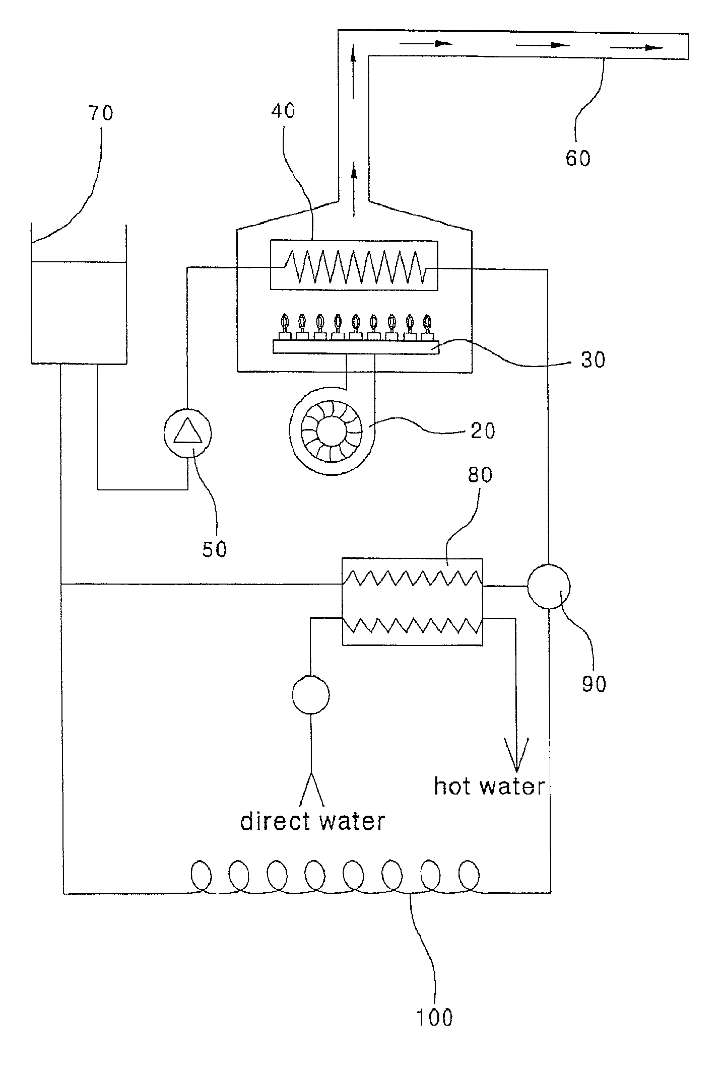
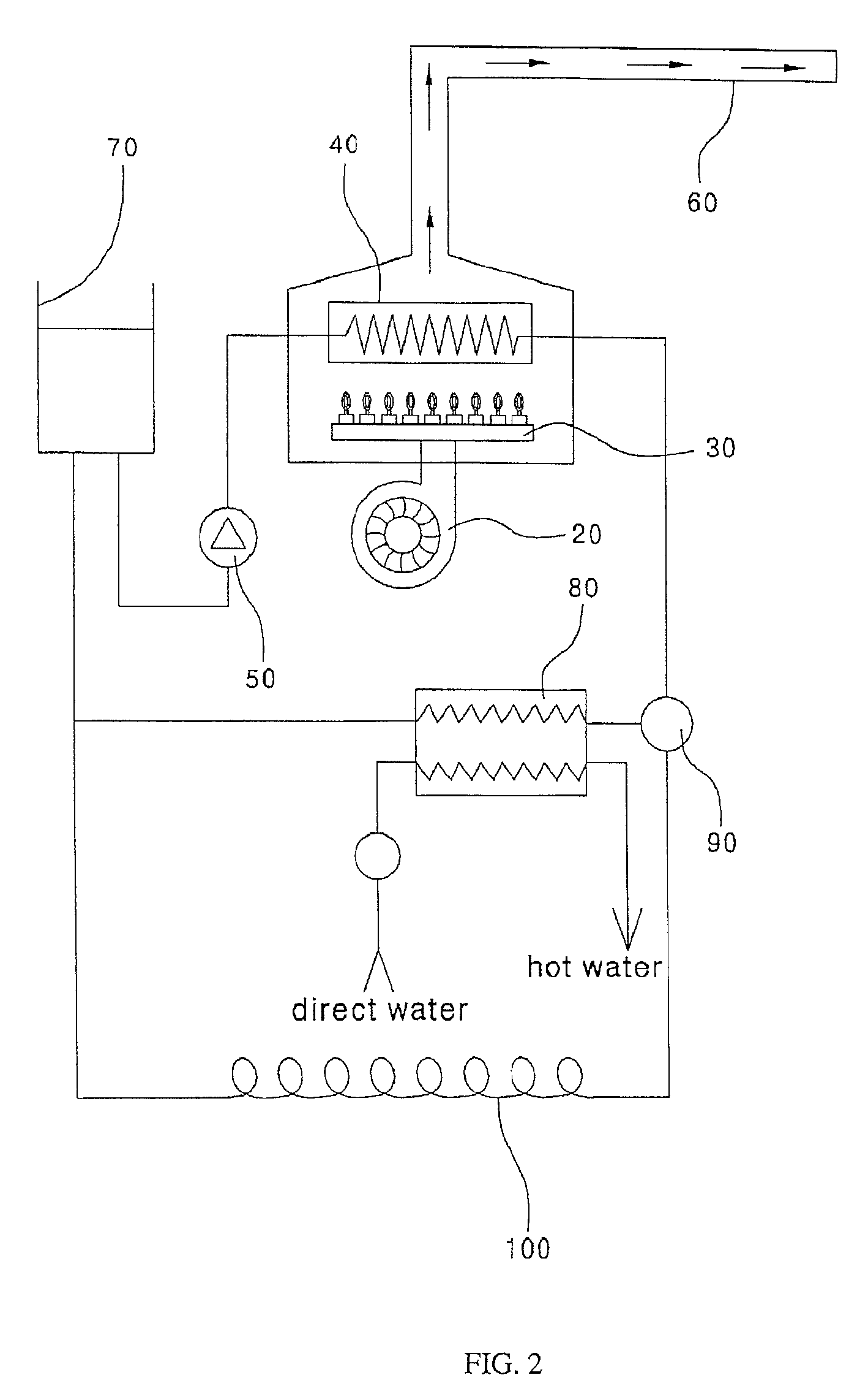
[0022]FIG. 2 is a schematic view illustrating a structure of a boiler employing a method for preventing coagulation according to an embodiment of the present invention, and FIG. 3 is a flowchart illustrating the method for preventing coagulation according to the embodiment of the present invention.

[0023]In order to implement a control method according to the present invention, an ambient air temperature detecting sensor (not shown) can be mounted outdoors or in an inlet of an air supply blower 20 of the boiler to detect the ambient air temperature.

[0024]First, the boiler is operated so as to execute a combustion stroke S201. In this case, an opera...


PUM


Abstract

A method and an apparatus are provided for preventing coagulation in an exhaust pipe of a boiler is provided. The method includes operating the boiler and executing a combustion stroke, determining if an ambient air temperature measured by an ambient air temperature detecting sensor is equal to or lower than a first temperature, shifting a 3-way valve to a hot-water location if the measured ambient air temperature is equal to or lower than the first temperature, executing an extinction stroke of a burner if the temperature of space heating water reaches a second temperature, and operating a circulation pump and a blower to exchange heat in a heat exchanger and to discharge warm air through an exhaust pipe, thereby preventing coagulation in the exhaust pipe of the boiler.

Description

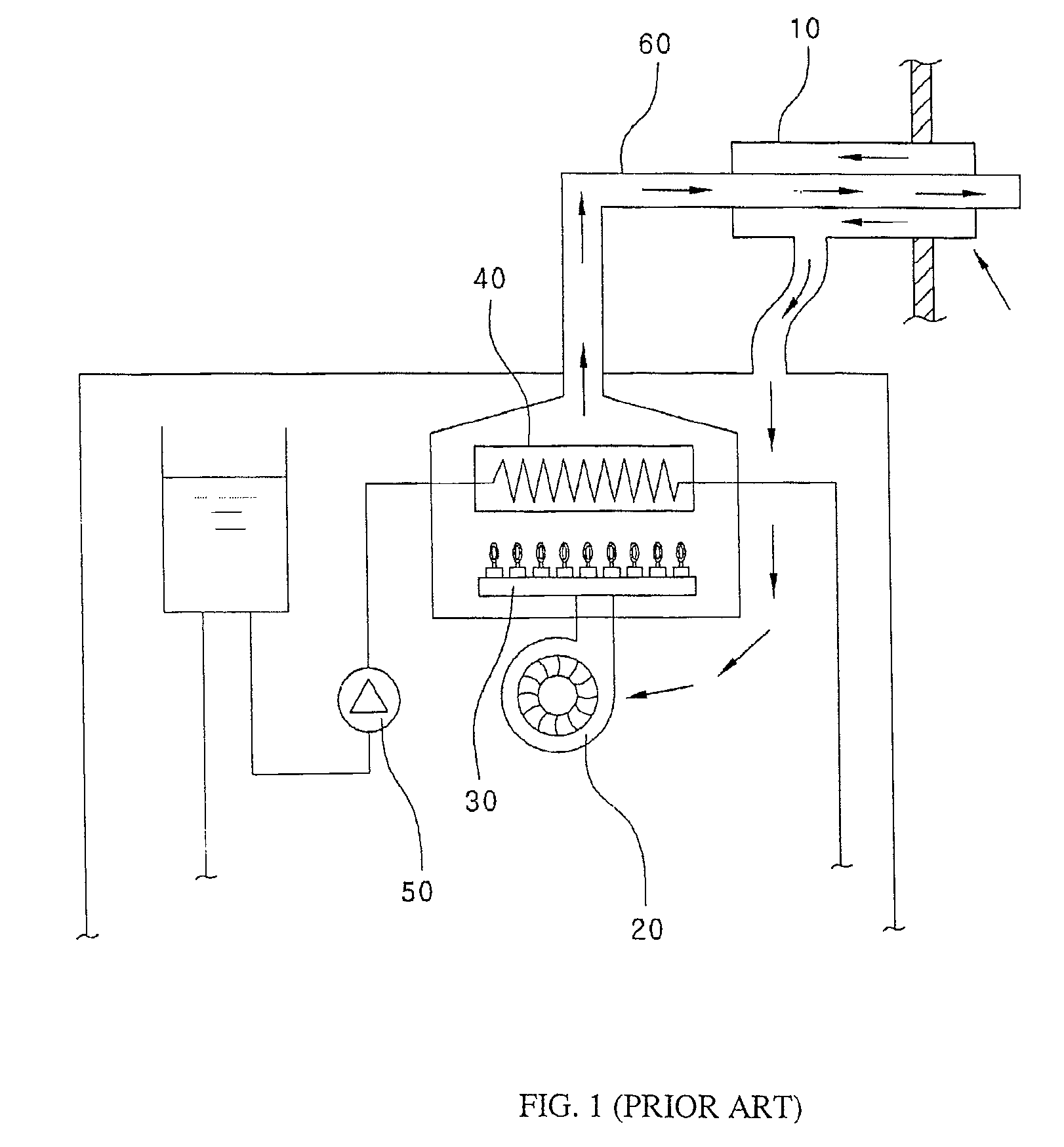
RELATED APPLICATIONS[0001]This is an U.S. National Phase Patent Application Under 35 USC §371 of International Patent Application No. PCT / KR2007 / 005091, filed on Oct. 17, 2007, which claims priority of Korean Patent Application No. 10-2006-0100753, filed on Oct. 17, 2006.BACKGROUND OF THE IVENTION[0002]1. Field of the Invention[0003]The present invention relates to a method for preventing coagulation of steam in an exhaust pipe of a boiler, and more particularly to a method for preventing coagulation in an exhaust pipe of a proportional control boiler, in which, when an ambient air temperature is equal to or lower than a predetermined temperature, the temperature of space heating pipe water is raised and a blower is then rotated to discharge warm air through the exhaust pipe, thereby preventing coagulation of steam and creation of icicles at an end portion of the exhaust pipe of the boiler.[0004]2. Discussion of Background Information[0005]FIG. 1 is a schematic view illustrating an ...

Claims


Application Information

Patent Timeline
Patent Type & Authority Patents(United States)
IPC IPC(8): F22B7/00
CPCF23N5/242F24H9/0036F24H9/2035F23N2025/13F23N2025/19F23N2225/13F23N2225/19F24H15/212F24H15/136F24H15/335F24H15/258F24H15/345F24H15/32F23J15/08F23J15/00F23J13/00
Inventor MIN, TAE SIK
Owner KYUNGDONG NAVIEN
Learn More