Multiple beam charged particle optical system

a technology of optical systems and charged particles, applied in particle separator tubes, radiation therapy, nanotechnology, etc., can solve the problems of high complexity of known lens structures or lens systems for at least partially correcting such aberrations, charge particle lenses, magnetic and/or electrostatic lenses, etc., to improve lithography systems and mitigate at least part of the

Active Publication Date: 2012-10-23
ASML NETHERLANDS BV
View PDF5 Cites 25 Cited by
  • Summary
  • Abstract
  • Description
  • Claims
  • Application Information

AI Technical Summary

Benefits of technology

[0015]It is further an object of the present invention to provide a versatile system that has various possibilities of correcting deviations and / or aberrations of the beam and / or beamlets.
[0066]Sensors for detecting or measuring of the position and orientation of the target are known in the art, and may comprise highly accurate laser interferometers. Such sensors or measuring systems may operate real time and can accurately determine the position and orientation of the target relative to the charged particle optical system or also denoted as ‘projection system’.

Problems solved by technology

A complication towards successful exposure lies in the fact that all components of the charged particle optics need to be highly accurate positioned in order guide the beamlets towards the desired position on the target.
A further complication for obtaining high resolution exposures lies in the fact that charged particle lenses, magnetic and / or electrostatic lenses, suffer from aberrations, in particular spherical aberrations.
Known lens structures or lens systems for at least partially correcting such aberrations are highly complex.
In this process very high accuracy is of prime importance, implying complex and expensive actuation and positioning means.
A further complication towards successful exposure lies in the fact that while the known charged particle system has means to compensate for errors in the XY-plane of the target using the deflection in the writing direction and the movement of the target holder, it is unable to correct for rotational errors using said deflection and movement of the target holder.
Said rotational errors, originating from misalignment around the Z-axis of the projection system and target, in fact from insufficient accuracy in the guidance of the stage in the X- and Y-direction respectively, ultimately result in a position error with this effect being increased when projection takes place further away from the centre of rotation, thereby increasing the accuracy requirements with regard to rotational errors for the target positioning system even further.

Method used


Image

  • Multiple beam charged particle optical system
  • Multiple beam charged particle optical system
  • Multiple beam charged particle optical system

Examples


Embodiment Construction

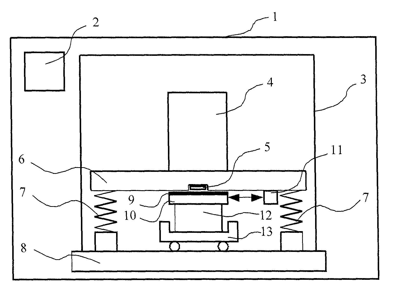
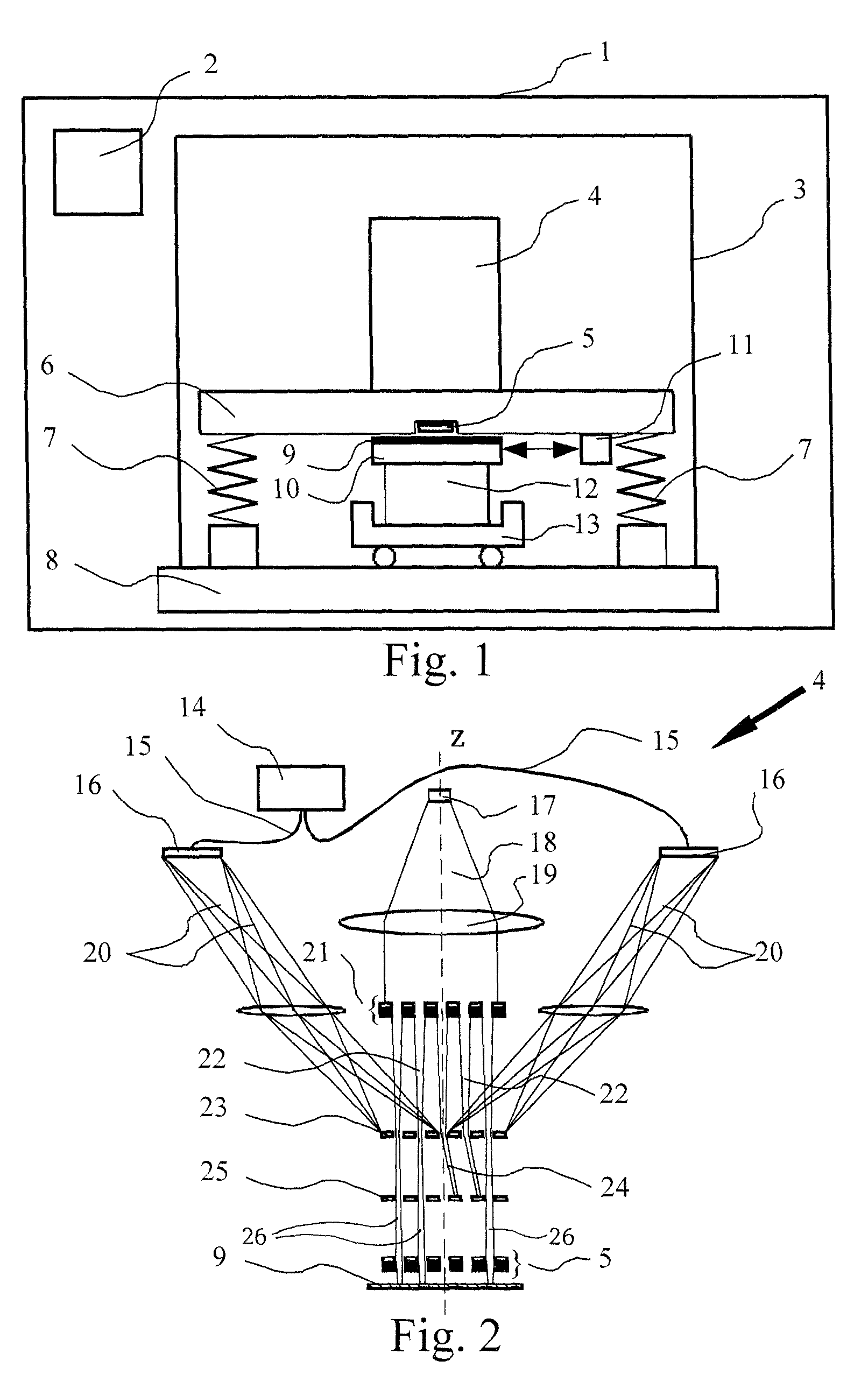
[0090]FIG. 1 is a schematic representation of a prior art charged particle system 1 for projecting an image or pattern, in particular an image or pattern provided by a control system 2, onto a target. In this design the charged particle system comprises a control system 2, a vacuum chamber 3 mounted on a base frame 8, which contains a charged particle column 4, a metro frame 6 and a target positioning system 10-13. The target 9 will generally be a wafer provided with a charged particle sensitive layer in the substrate plane. Target 9 is placed on top of wafer table 10, which are in turn place on chuck 12 and long stroke drive 13. Measurement system 11 is connected to metrology frame 6 and provides measurements of the relative positioning of wafer table 10 and metro frame 6. The metro frame 6 typically is of relatively high mass and is suspended by vibration isolators 7 for example embodied by spring elements in order to dampen disturbances. The electron optical column 4 performs a f...


PUM


Abstract

The invention relates to a multiple beam charged particle optical system comprising:a charged particle source for generating a plurality of charged particle beamlets, andcharged particle optics for directing the charged particle beamlets from the charged particle source towards a target, wherein each charged particle beamlet defines a beamlet center line, said charged particle optics comprising one or more electrostatic lens arrays, each comprising two or more array electrodes for generating a plurality of electrostatic lenslets, wherein each lenslet is arranged for focusing a corresponding charged particle beamlet, and wherein each lenslet defines a lenslet optical axis, wherein at least one of said one or more electrostatic lens arrays comprises one or more off-axis electrostatic lenslets, wherein the beamlet center line of the corresponding charged particle beamlet passes through said off-axis electrostatic lenslet at a distance from its lenslet optical axis.

Description

[0001]This is a non-provisional application claiming the benefit of U.S. Provisional Application No. 61 / 243,948 filed Sep. 18, 2009.BACKGROUND[0002]The invention relates to a multiple beam charged particle optical system comprising:[0003]a charged particle source for generating a plurality of charged particle beamlets,[0004]charged particle optics for directing the charged particle beamlets from the charged particle source towards a target, said charged particle optics comprising one or more electrostatic lens arrays, each comprising two or more array electrodes for generating a plurality of electrostatic lenslets, wherein each lenslet is arranged for focusing a corresponding charged particle beamlet.[0005]Such a system is for example employed in a maskless charged particle beam lithography assembly for projecting one or more charged particle beamlets onto a target for writing an image or pattern onto said target.PRIOR ART[0006]One example of such a system, disclosed in WO2007 / 01380...

Claims


Application Information

Patent Timeline
Patent Type & Authority Patents(United States)
IPC IPC(8): G21K1/08
CPCB82Y10/00B82Y40/00H01J37/12H01J37/1477H01J37/3174H01J2237/0435H01J2237/04924H01J2237/1205H01J37/317H01J37/147
Inventor KRUIT, PIETERZONNEVYLLE, AERNOUT CHRISTIAAN
Owner ASML NETHERLANDS BV
Why Eureka
Try Eureka