Unidirectionally-energized brushless DC motor including AC voltage output winding and motor system

a brushless dc motor and output winding technology, applied in the direction of diagnostic recording/measuring, magnetic circuit rotating parts, shape/form/construction, etc., can solve the problem of not being able to obtain continuous electric force, and achieve the effect of large torque, long feeding time and wide width

Inactive Publication Date: 2012-10-23
KOMATSU YASUHIRO +3
View PDF4 Cites 4 Cited by
  • Summary
  • Abstract
  • Description
  • Claims
  • Application Information

AI Technical Summary

Benefits of technology

[0016]The large-value narrow-angle torque in which the electromagnetic torque has the large value and the small-value wide-angle torque in which the generated rotation angle has the large width are generated. Accordingly, the large torque is obtained with the small electric power when the electric power is supplied to the first winding at the time the large-value narrow-angle torque is generated. The feeding time can be lengthened when the electric power is supplied to the first winding at the time the small-value wide-angle torque is generated. Therefore, the current passed through the first winding can be increased, even if the time necessary to the increase and decrease in current passed through the first winding is lengthened due to self-inductance of the electromagnet including the first magnetic core and the first winding.
[0017]According to another embodiment, the unidirectionally-energized brushless DC motor includes the two disks, the polarity of the permanent magnet disposed in one of the disks and the polarity of the permanent magnet disposed in the other disk are different from each other, and the first magnetic core is fixed such that one of end portions corresponds to the permanent magnet disposed in one of the disks while the other end portion corresponds to the permanent magnet disposed in the other disk. Accordingly, because both the electromagnetic forces generated in the two end portions of the first magnetic core can be utilized to rotate the disk, the electric power-mechanical power energy conversion efficiency can be enhanced.
[0018]According to another embodiment, the first magnetic cores are fixed in a certain position of the disk and a position that is separated from the position by 180° so as to be opposite each other, and the second magnetic cores are fixed in a certain position of the disk and a position that is separated from the position by 180° so as to be opposite each other, and the identical current is passed through the two windings that are opposite each other. Therefore, the electromagnetic force in the radial direction is cancelled, so that a vibration can be decreased to reduce a noise.
[0019]According to another embodiment, the frame and the disk are made of the non-metallic material, so that an iron loss can be reduced.
[0020]According to another embodiment, when the disk is stopped because the electric power is not supplied to the first winding, the second magnetic core is located with respect to the permanent magnet such that the positional relationship between the first winding and the permanent magnet becomes the positional relationship in which the torque in the normal direction of the disk or the torque in the reverse direction of the disk is continuously generated at the predetermined rotation angle of the disk when the supply of the electric power to the first winding is started. Accordingly, when the power feeding to the first winding is started in the stable equilibrium state in which the disk is stopped, the disk can immediately be rotated in the normal direction or the reverse direction.

Problems solved by technology

Accordingly, in the magnetic rotation motor power generator, unfortunately the electromotive force cannot continuously be obtained.

Method used


Image

  • Unidirectionally-energized brushless DC motor including AC voltage output winding and motor system
  • Unidirectionally-energized brushless DC motor including AC voltage output winding and motor system
  • Unidirectionally-energized brushless DC motor including AC voltage output winding and motor system

Examples


Embodiment Construction

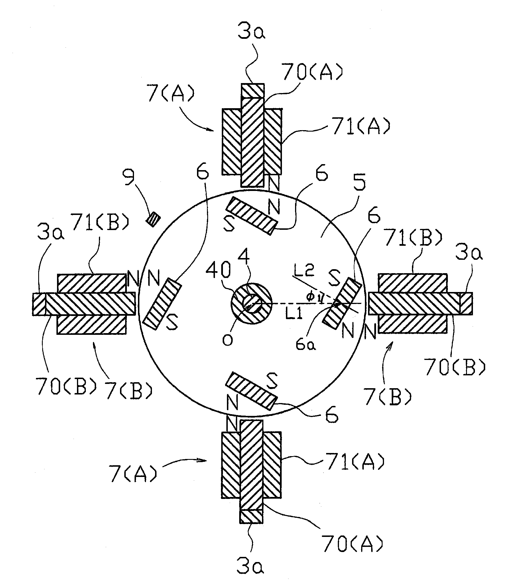
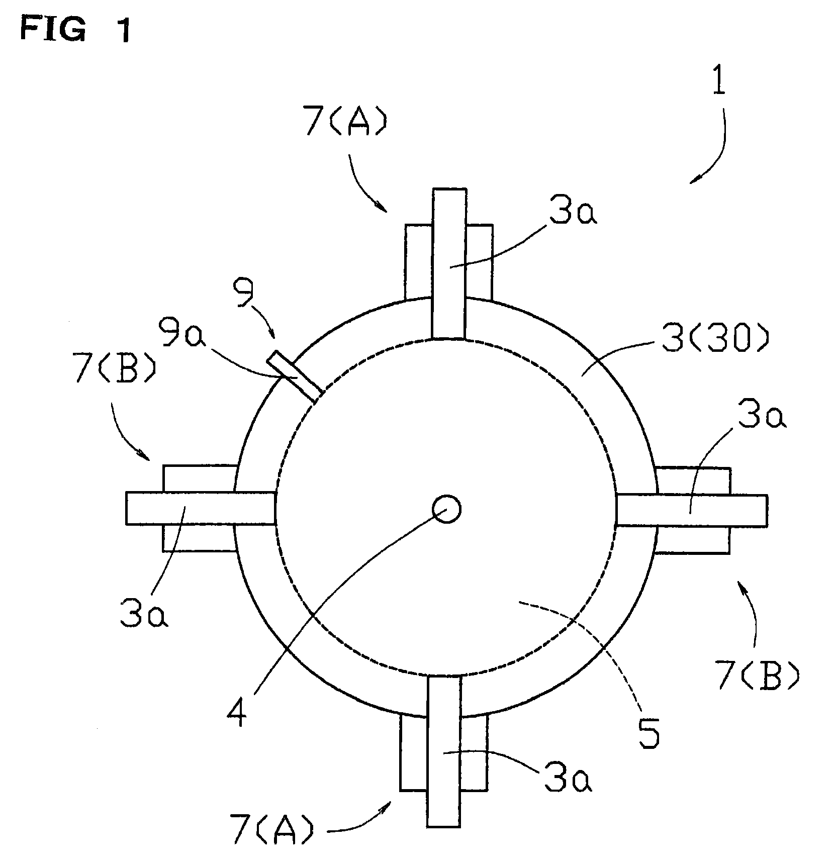
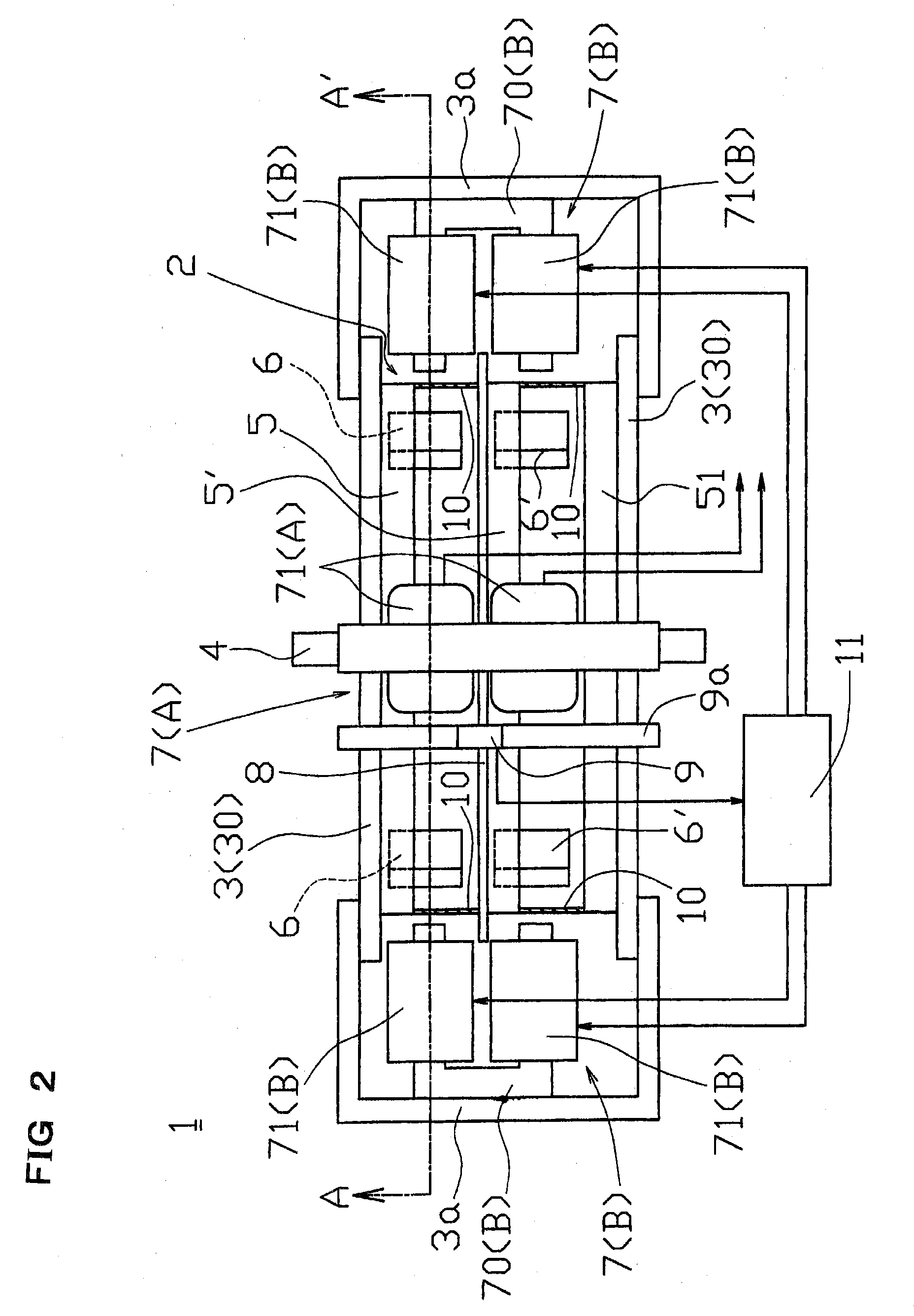
[0043]A unidirectionally-energized brushless DC motor 1 (hereinafter referred to as “brushless DC motor”) including an AC voltage output winding according to the present invention will be described below with reference to the drawings. As illustrated in FIGS. 1 to 3, the brushless DC motor 1 of the present invention includes a rotating body 2 and a frame 3 that supports the rotating body 2. The rotating body 2 has a structure in which two disks 5 and 5′, one disk 51, and one position detecting disk 8 are fixed at predetermined intervals to a shaft 4 that constitutes a rotation axis while a spacer 40 is interposed therebetween. In one of surfaces of each of the disks 5 and 5′, four permanent magnets 6 and 6′ are provided at equal intervals in a periphery of the disks 5 and 5′. On the other hand, in the frame 3, four electromagnets 7 are fixed by a support member 3a according to four sets of permanent magnets 6 in which one set includes two permanent magnets 6. Although described late...


PUM


Abstract

A unidirectionally-energized brushless DC motor includes a disk attached to a frame, a plurality of plate-like permanent magnets disposed on the disk at equal intervals around the disk, magnetic cores fixed to the frame according to the plurality of permanent magnets, windings each of which is wound around the magnetic core and to which DC power is supplied, a predetermined number of magnetic cores fixed to the frame, and windings each of which is wound around the magnetic core and connected to a power consumption device. The permanent magnets are located such that an angle formed by a straight line passing through the center of the disk and the center of the permanent magnet and a normal line in the center of a magnetic pole plane of the permanent magnet ranges from 0° to 60°.

Description

CROSS REFERENCE TO RELATED APPLICATION[0001]This application is the 35 U.S.C. §371 national stage of PCT application PCT / JP2007 / 071826, filed Nov. 9, 2007, the disclosure of which is hereby incorporated by reference.TECHNICAL FIELD[0002]The present invention relates to a unidirectionally-energized brushless DC motor including an AC voltage output winding and a motor system, particularly to a unidirectionally-energized brushless DC motor including an AC voltage output winding, the brushless DC motor rotating a rotating body to act as a motor and directly generating electric power by the rotation of the rotating body, and a motor system including the brushless DC motor.BACKGROUND ART[0003]Conventionally a motor and a power generator are mechanically coupled when electric power is generated by rotating the motor. Originally the motor and the power generator have the same structure, those are called the motor when a rotating body is rotated to obtain a driving force by supplying the ele...

Claims


Application Information

Patent Timeline
Patent Type & Authority Patents(United States)
IPC IPC(8): H02K21/12H02K21/14H02K47/02H02N11/00
CPCA61B5/0488A61B5/4893A61B8/00H02K1/2746H02K21/14H02K47/04H02K53/00H02P25/02H02K2201/12A61B5/389
Inventor KAMIDA, YOSHIHIDEKOMATSU, YASUHIRO
Owner KOMATSU YASUHIRO
Why Eureka
Try Eureka