Eureka AIR delivers breakthrough ideas for toughest innovation challenges, trusted by R&D personnel around the world.

Microprocessor controlled automated mixing system, cogeneration system and adaptive/predictive control for use therewith

Inactive Publication Date: 2012-10-30
HYCOGEN POWER
View PDF37 Cites 17 Cited by
  • Summary
  • Abstract
  • Description
  • Claims
  • Application Information

AI Technical Summary

Benefits of technology

[0016]In another aspect, another embodiment provides a system and method having adaptive and predictive capabilities to improve the usage of bio-fuel in combination with at least one of hydrogen and / or natural gas or propane gas.
[0022]Another object of one embodiment is to provide a system and method for automatically extracting, cleansing, purifying and converting bio-fuel on-site and blending it with natural gas, propane and hydrogen to produce a high-efficiency gaseous fuel for combustion or spark ignited-type engines or turbine engines that result in increased fuel efficiency with a drastic decrease in harmful emissions. Simultaneously, a microprocessor programmed with control algorithms determines the most efficient use of the fuels and processes. This and other embodiments can result in a decreased reliance on the public utility grid.
[0023]The apparatus and method have means for predicting user needs and adapting the mixture in response to various inputs and factors, such as availability of bio-fuel. The resulting renewable fuel is highly efficient and drastically reduces emissions of NOx, CO and CO2. Additional to this super fuel is the ability, via microprocessors or PLCs with various algorithms, to Adapt, Predict and Learn (APL) the most energy efficient usages of said fuels with compression ignition or spark ignited engines or turbine engines in various applications, including but not limited to, cogeneration or combined heat and power (CHP) applications working in parallel with the utility grid while reducing the reliance on outdated and heavily taxed utility grid.
[0026]In yet another aspect, another embodiment comprises a method for reducing emissions associated with use of electricity at a location that receives electricity from a power grid, the method comprising the steps of supplying natural gas or propane, hydrogen and bio-fuel to an internal combustion engine or turbine engine in a predetermined fuel ratio; the internal combustion engine or turbine engine being coupled to a generator for generating electricity at the location, sensing at least one condition relating to the internal combustion engine or turbine engine or its use and causing a plurality of valves to be actuated to provide the natural gas or propane, hydrogen and bio-fuel to the internal combustion engine or turbine engine in the predetermined fuel ratio and in response to the at least one condition in order to facilitate reducing carbon footprint of the location.

Problems solved by technology

PM emissions, among other detrimental health effects, have been linked to increased cardiovascular mortality rates and impaired lung development in children.
However, with direct injection engines that are fueled with natural gas, it has been found that there is a trade-off between NOx emissions and emissions of unburned hydrocarbons and PM.

Method used


Image

  • Microprocessor controlled automated mixing system, cogeneration system and adaptive/predictive control for use therewith
  • Microprocessor controlled automated mixing system, cogeneration system and adaptive/predictive control for use therewith
  • Microprocessor controlled automated mixing system, cogeneration system and adaptive/predictive control for use therewith

Examples


Embodiment Construction

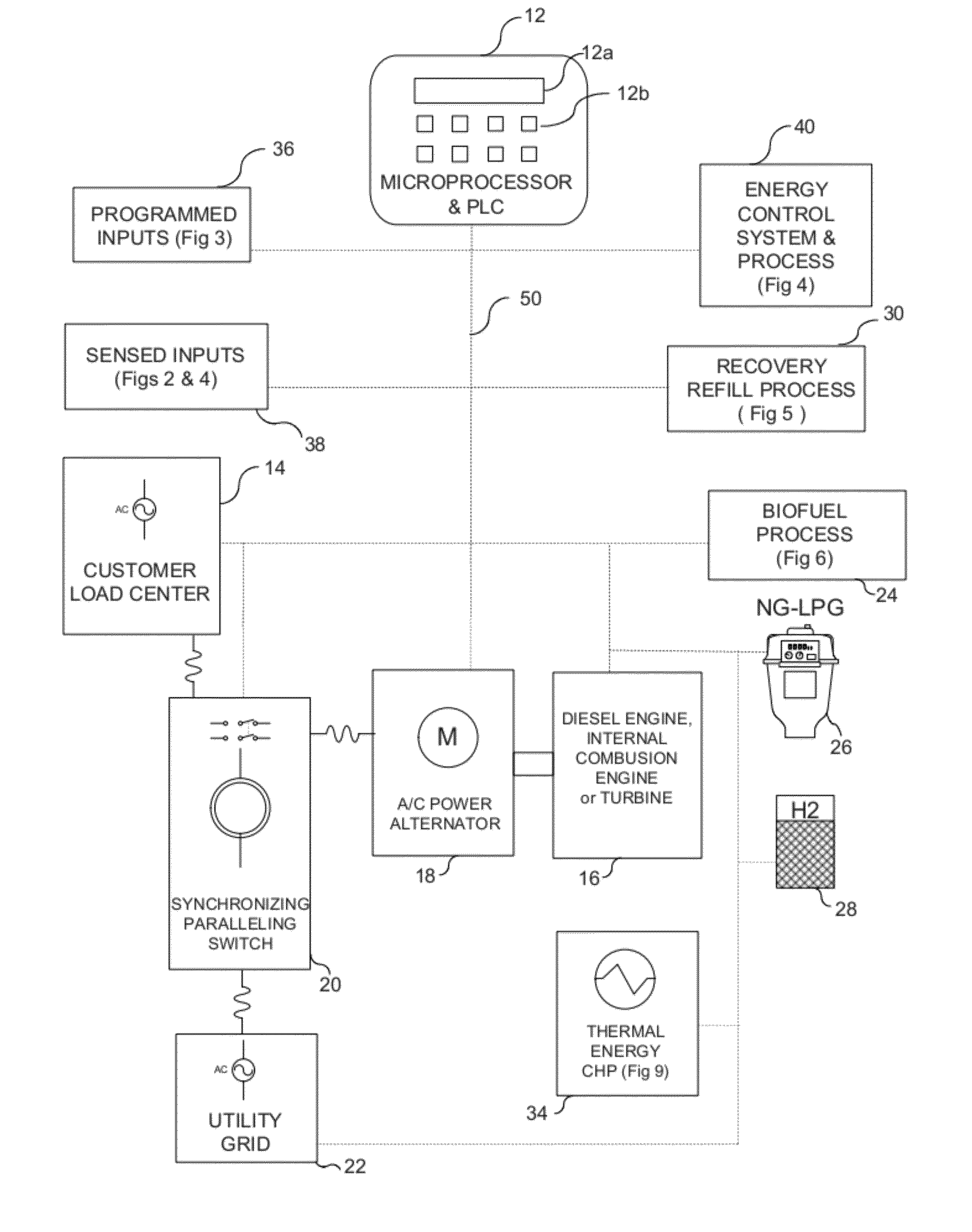
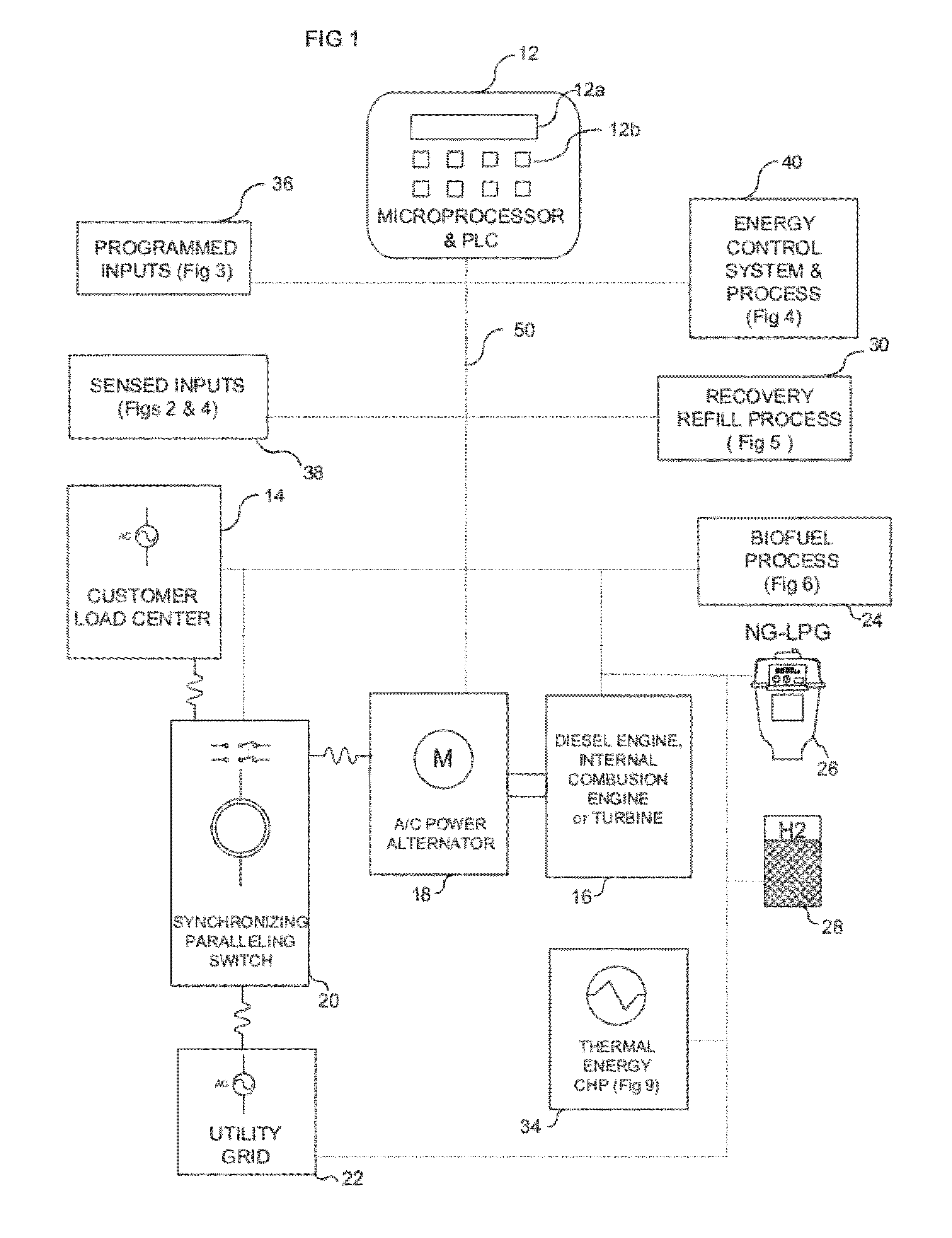
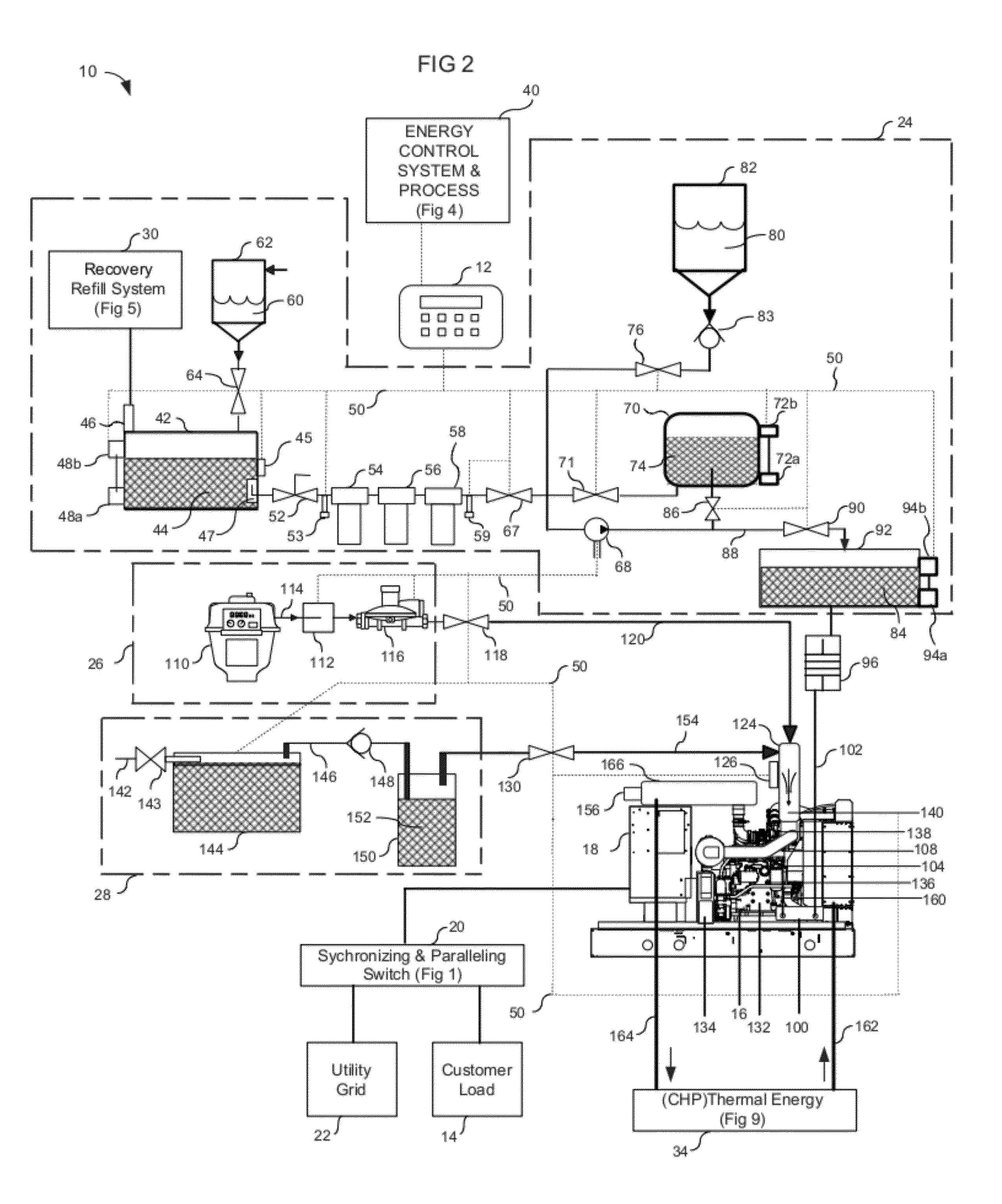
[0085]Referring now to FIGS. 1-10, an automated microprocessor controlled multi-fuel mixing cogeneration system 10 is shown. In the embodiment being described, the multi-fuel mixing cogeneration system 10 blends hydrogen, bio-fuel, biodiesel / diesel fuel and / or natural gas or propane in a predetermined ratio to provide a highly efficient cogeneration system for efficiently using various fuel sources in a manner that minimizes cost, facilitates reducing emissions of NOx, CO and CO2 emissions, and decreases the dependence on a conventional utility power grid. The bio-fuel mixture may or may not comprise an additive, such as a thinning combustion additive of the type described later herein. In the illustration being described, the cogeneration system 10 and methods described herein provide automated delivery of the various gases and / or fuel, automated blending, monitoring and controlling of the mixtures of such fuels for a fuel to be used by the cogeneration system 10. The system 10 fac...


PUM


Abstract

A microprocessor controlled automated, multi-fuel apparatus to blend hydrogen, bio-fuel and / or natural or propane gases. This novel multi-stage apparatus first converts cooking oils into bio-fuel. The system automatically blends the bio-fuel with at least one of or both hydrogen gas, generated by a self-contained on-board hydrogen electrolyzer, and / or natural or propane gases. This blended “Hyenrich” gaseous fuel drives various processes including, but not limited to, cogeneration systems and electrical generators to produce “green” electricity by utilizing an adaptive and predictive learning algorithms to significantly reduce cost per kilowatt and lessen dependency on the over taxed utility grid, while simultaneously reducing emissions of CO, CO2 and NOx, making the method and apparatus an environmentally-friendly energy device.

Description

BACKGROUND OF THE INVENTION[0001]1. Field of the Invention[0002]This invention relates to improvements of multiple fuel blending. More particularly, it relates to an apparatus and method for automatically using and converting various waste cooking oils, including but not limited to, variations of vegetable, peanut and pressed oils, into usable bio-fuel while simultaneously and automatically blending this fuel with natural gas or propane and hydrogen in a predetermined ratio that is adapted and predicted based on historical and actual use data.[0003]2. Description of the Related Art[0004]For many years, industry has been interested, on the one hand, in alternative energy sources that are not based on fossil deposits, and on the other hand, in so-called “renewable raw materials.” The latter include in particular plant oils, or in other words, fatty acid esters, usually triglycerides, which in general can be classified as bio-degradable and environmentally harmless.[0005]Various enviro...

Claims


Application Information

Patent Timeline
IPC IPC(8): G06G7/70B60L50/10
CPCG05B19/042G05B2219/25387G05B2219/2639Y02B70/3241Y04S20/227Y02B70/30Y04S20/20
Inventor SAGAR, CHRISTOPHER LEEMASKREY, ERIC MICHAEL
Owner HYCOGEN POWER
Why Eureka
Eureka Blog
Learn More