Inter/pre-cured layer/pre-cured embroidered composite laminate and method of producing same

a composite laminate and layer technology, applied in the field of pre-curing layer/pre-curing embroidered composite laminate and the field of producing same, can solve the problems of increasing brittleness, affecting the quality of embroidered fabrics, and limiting the process to relatively thin layers, so as to achieve the effect of enhancing the strength of embroidered fabrics between layers

Inactive Publication Date: 2012-11-20
FREE JAMES J
View PDF7 Cites 37 Cited by
  • Summary
  • Abstract
  • Description
  • Claims
  • Application Information

AI Technical Summary

Benefits of technology

[0039]When embroidering is done, the glue-strength between the layers is additionally enhanced by means of the tensile strength of the composite fibers that are used in the stitching. The strength of stitching between laminates will vary between that slightly above the glue-strength of the resin (as would be obtained by occasional stitching between the layers), to the aggregate tensile strength of the combined fibers totally packed in the direction normal to the laminate (as would be seen with maximally stitching a laminate in the Z direction).

Problems solved by technology

More diverse types of resins such as thick viscous epoxy can be used when involving this process, however the process still is mostly limited to fairly thin layers of laminate per pass or per bagging.
The challenge with RTM processes is that the resin must diffuse very easily and most likely it would need to be thin.
The problem with this is when the resin chemically cures there is a likelihood that it shrinks and the ratio of fiber to volume would be less than with thick-pass layers, and there could be increased brittleness.
Shrinkage even has consequences on surface quality: a large amount of shrinkage will cause “print-through” where the pattern of the shallowest layer shows up on the surface of the part.
A real low-viscosity resin will wet out more layers or thickness, but will tend to shrink more.
And, as in a point load in the center of a beam supported at each end, there is a case where large amounts of sheering could take place at the supported ends and cause failure by splitting with unidirectional fibers and glue strength, or sheering between the top wall and bottom wall in a braided “tube” like structure.
The problem with all these processes is that extra layers of laminate or passes have to be made.
If the fiber fails to locally get wet out or to a lesser effect, has air bubbles, the whole structure is weakened, not to mention coming up short of other properties like water tightness or aesthetic appeal.
A 10 mil tape of carbon fiber will be thin because the intended resin to use with it, epoxy is very viscous, thick and difficult to handle.
If layers were able to be tacked in advance with the tacking allowed to dry as in Youngkeit, (U.S. Pat. No. 4,938,824 Jul. 3, 1990) there could be a large risk of air or voids around the places where previous resin had dried and where it would have to be against newly-curing wet resin.
Further causes include differences or changes in properties which may include brittleness, ductility, elasticity, etc.
However, there is no mention of pre-wetting out the fibers which would lead to rapid drop in performance as the fibers could easily get frayed given abrasion, vibration, etc.
This and other like methods to prevent de-lamination would deposit extra metal in the laminate producing a heavier part than embroidering, and not work as effectively.
A method of wrapping the perimeter of a laminate will not solve the problems that embroidering could, of a de-lamination of, say, a de-laminating T strut.
Filament winding can provide lots of skin strength, and hoop strength, however, it is somewhat limited to geometric continuity.
It would be very difficult to wind complex shapes and the process does not lend itself to strengthening particular localities.
Also, winding alone would not lend itself to having connecting spars that provide wall to wall strength, upper to lower surface strength, and the like, i.e. keeping the opposite walls from expanding apart from each other at poles.
Simply drilling a hole here would fray the braid, and surely weaken the pultruded braided cylinder.
5. And therefore soluble matrix stitching would not be able to improve upon the delaminating and or peel strength of the cured composition as the stitching of reinforcement fibers would.

Method used


Image

  • Inter/pre-cured layer/pre-cured embroidered composite laminate and method of producing same
  • Inter/pre-cured layer/pre-cured embroidered composite laminate and method of producing same
  • Inter/pre-cured layer/pre-cured embroidered composite laminate and method of producing same

Examples


embodiment # 2

ALTERNATIVE EMBODIMENT #2

[0106][FIG. 22] represents the or sandwiching of foreign material such as foam or like core material (i.e. hollow “Hexcell”®, pumice-like “Klegecell”®, etc.) (38) where outside layers (1) and (2) are sewn together and through the foam (38) in order to encapsulate the foam within the laminate. Embroidered fibers (4) hold outer layers (1,2) towards each other in tension

PREFERRED OPERATION

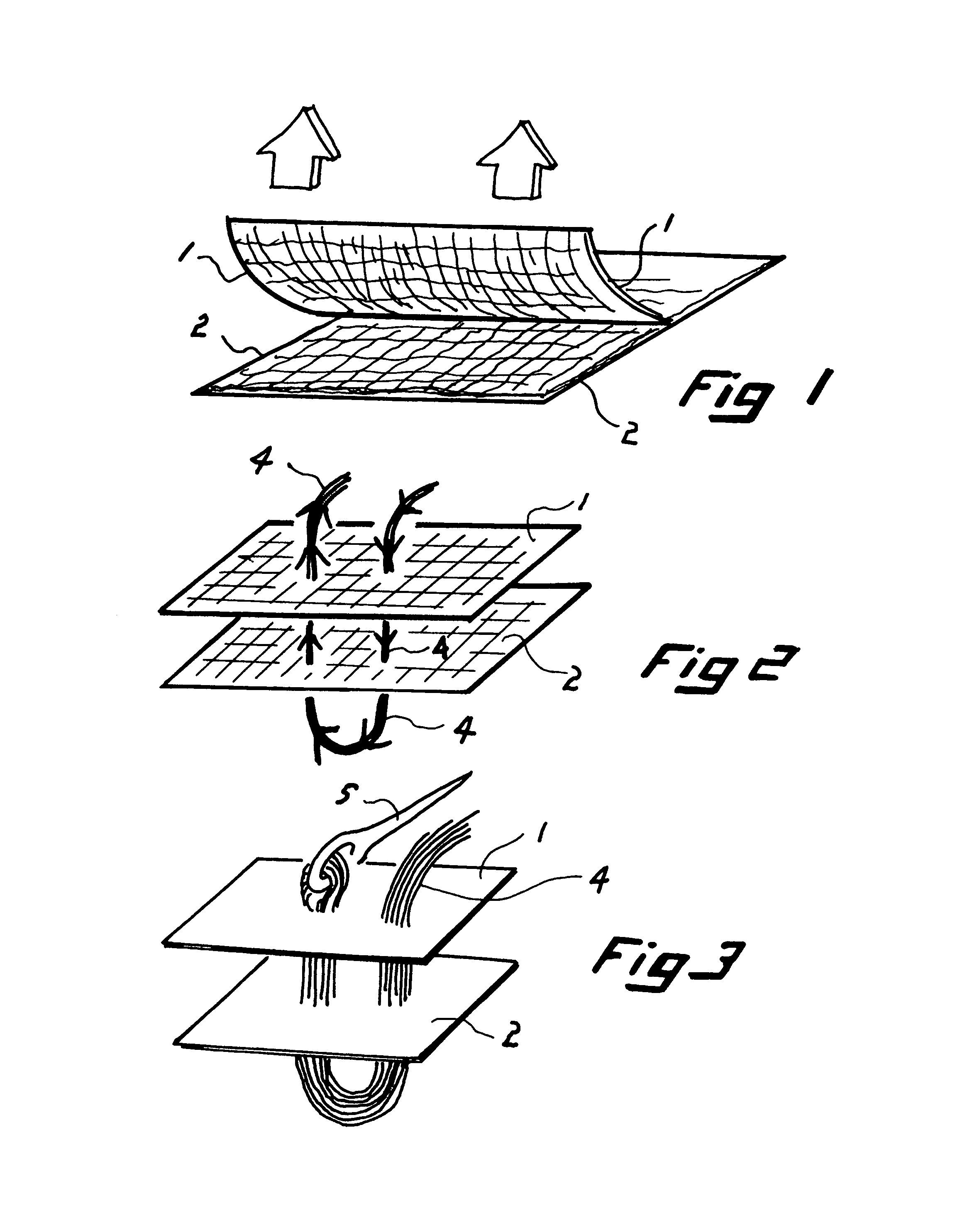
[0107]While practical or symbolic needle (5) in [FIGS. 1,2] pulls fiber bundle / tow (4) through outer layers (1,2) in [FIGS. 1,2], fibers in tow are wetted out or pre-cured (39) in [FIG. 23]. As fiber bundle tow is pulled (embroidered, sewn, tied, needle pointed, and so on), (40), the laminate that is being stitched together (9) is also wet or pre-cured. Said tow (4) is pulled tight enough to make the stitch fast, yet not so tight that it would prevent proper wet-out or impregnation. Tow (4) and laminate (9) are allowed to settle, to be rolled out, to be vacuum-bagged, interfer...

embodiment # 3

ALTERNATIVE EMBODIMENT #3

[0108][FIG. 24] represents a progressively stitched laminate as similar to [FIG. 10] except with base layer (1), progressive layers (10, 11 through 14) being stitched into heterogeneous i.e. metallic substrate (43) through mechanical loops, knobs, dovetail, edge, bowl with a cornice-rim, etc. (43) or through heterogeneous laminated substrate mechanical loop, knob, dovetail, edge, bowl with cornice rim, etc. (44) including looping, wrapping, etc. fibers (45) wherein heterogeneous materials with diverse mechanical, thermo-mechanical, chemical, etc. properties may still remain joined despite being subject to extreme conditions, and extreme chemical, physical, dimensional changes in said heterogeneous materials

embodiment # 4

ALTERNATIVE EMBODIMENT #4

[0109][FIG. 26] represents a thermal heat barrier that could just as easily be chemical, liner, or explosive ceramic armor assemblies. Insulating, refractory, etc. pre-hardened blocks (46) are wet-sewn to wet layer (or pre-cured in pre-fired ceramic), (1) in [FIG. 27], sewn and held there by loops, knobs, etc. in the blocks (43). The blocks can be pre-hardened composite, cast or fabricated heterogeneous material i.e. metallic, and may employ a grouting material (47) if need be. When heat is applied (49), blocks (46) expand [FIG. 28] as shown by graduations (48a) compared to those while cooled (48) in [FIG. 27] and grouted joint (47) is pinched tighter.


PUM

PropertyMeasurementUnit
thickaaaaaaaaaa
thickaaaaaaaaaa
glue strengthaaaaaaaaaa

Abstract

Methods of pre-cured (wet-out) composite lay up, are improved upon by embroidering, sewing, stitching, bundle-wrapping, tying, etc., substantially between layers and substantially normal, or in the “Z-direction” to the lay up with a wet or pre-cured fiber bundle or tow. The pre-cured tow is embroidered, etc. either in with a like, homogeneous wet to wet layering or a heterogeneous non-similar layering, between double or multiple layers. Heterogeneous examples include differing material types among layers, laying and embroidering in objects or voids, as well as wet-laminating/sewing in with an already-dry (set/cured) layer.

Description

[0001]This application claims benefit of Provisional Application No. 60 / 879,105 filed Jan. 8, 2007STATEMENT REGARDING FEDERALLY SPONSORED RESEARCH AND DEVELOPMENT[0002]Not applicable[0003]RESEARCH1,216,265BakelandFeb. 20, 19172,692,219Slayter et alOctober 1954154 / 442,762,739WeissSep. 11, 1956154 / 903,837,985ChaseSep. 24, 1974161 / 554,109,435LoydAug. 29, 1978523 / 0914,196,251WindeckerApr. 1, 1980428 / 3114,350,728Haung, et alSep. 21, 1982428 / 1054,469,541GoldsworthySep. 4, 1984156 / 1804,808,461Boyce, et alFeb. 8, 1989428 / 1194,938,824YoungkeitJul. 3, 1990156 / 1735,186,776Boyce, et alFeb. 16, 1993156 / 7325,350,614Chase et alSep. 27, 1994428 / 535,456,974Lundband et alOct. 10, 1995428 / 2295,466,506FreitasNov. 14, 1995428 / 1055,512,348MazelskyApr. 30, 1996428 / 1025,589,015,FuscoDec. 31, 1996156 / 7315,869,165RorabaughFeb. 9, 1999428 / 1056,277,463Hamilton et alAug. 21, 2001428 / 1066,599,610Homma, et al,Jul. 29, 2003428 / 1026,932,116Smith, et alAug. 23, 2005138 / 987,192,634Carter, et alMar. 20, 2007428 / 113ser...

Claims


Application Information

Patent Timeline
Patent Type & Authority Patents(United States)
IPC IPC(8): D05B93/00B32B9/00
CPCB32B5/06B32B5/10D05B93/00D05C17/00B29C70/24Y10T428/24033B32B2260/046B32B2305/076B32B2260/023
Inventor FREE, JAMES J
Owner FREE JAMES J
Why Eureka
Try Eureka