Method and apparatus for evaluating dielectrophoretic intensity of microparticle

a technology of dielectrophoretic intensity and evaluation method, which is applied in the direction of fluid pressure measurement, liquid/fluent solid measurement, peptide measurement, etc., can solve the problem that the microscopic observation cannot be applied to nanoparticles with particle sizes below the optical microscopic observable limit, and achieve the effect of improving the s/n of measuremen

Inactive Publication Date: 2012-11-20
SHIMADZU CORP
View PDF6 Cites 0 Cited by
  • Summary
  • Abstract
  • Description
  • Claims
  • Application Information

AI Technical Summary

Benefits of technology

[0008]The conventional particle evaluation method by dielectrophoresis using video observation of fluorescent particles as described above has the following three disadvantages.
[0020]In general, since the light diffracted from each groove of the diffraction grating is interfered and added in the same phase, signals are increased as the square of the number of grooves, and in the method of the present invention, thus, the sensitivity of measurement can be enhanced by increasing the number of grooves. Therefore, even a particle with small particle diameter can achieve a detection level if a number of such particles collect to form a diffraction grating. It is ascertained that, according to the method of the present invention, dielectrophoretic characteristics can be measured even for microparticles of several nanometers in diameter which are naturally low in dielectrophoretic effect due to the advantages of no need of phosphor, enhanced quantitative determination property, and further improved sensitivity, compared with the conventional evaluation method of dielectrophoresis.
[0027]When such comb-like electrodes are arranged, each comb-like electrode is formed so that an electrode piece eccentrically-located area including at least two linear electrode pieces disposed adjacently to each other, and an electrode piece absent area free from electrode pieces are alternately located, and a pattern in which each comb-tooth electrode is disposed so that the electrode piece eccentrically-located area of one comb-like electrode is located in the electrode piece absent area of the other comb-like electrode can be more suitably adopted. By using such electrodes, the pitch of high-density area of particles dielectrically migrated and captured due to formation of the AC electric field by application of AC voltage becomes larger than the pitch of each electrode piece. As a result, the grating pitch of density distribution-induced diffraction grating of the particles becomes larger than the grating pitch of diffraction grating formed by the electrode pieces, and the outgoing directions of diffracted light can be differed between both the diffraction gratings. Thus, the diffracted light by density distribution of the particles can be selectively detected to improve S / N of measurement.

Problems solved by technology

However, the microscopic observation cannot be applied to nanoparticle with a particle size below an optical microscopic observable limit.

Method used


Image

  • Method and apparatus for evaluating dielectrophoretic intensity of microparticle
  • Method and apparatus for evaluating dielectrophoretic intensity of microparticle
  • Method and apparatus for evaluating dielectrophoretic intensity of microparticle

Examples


Embodiment Construction

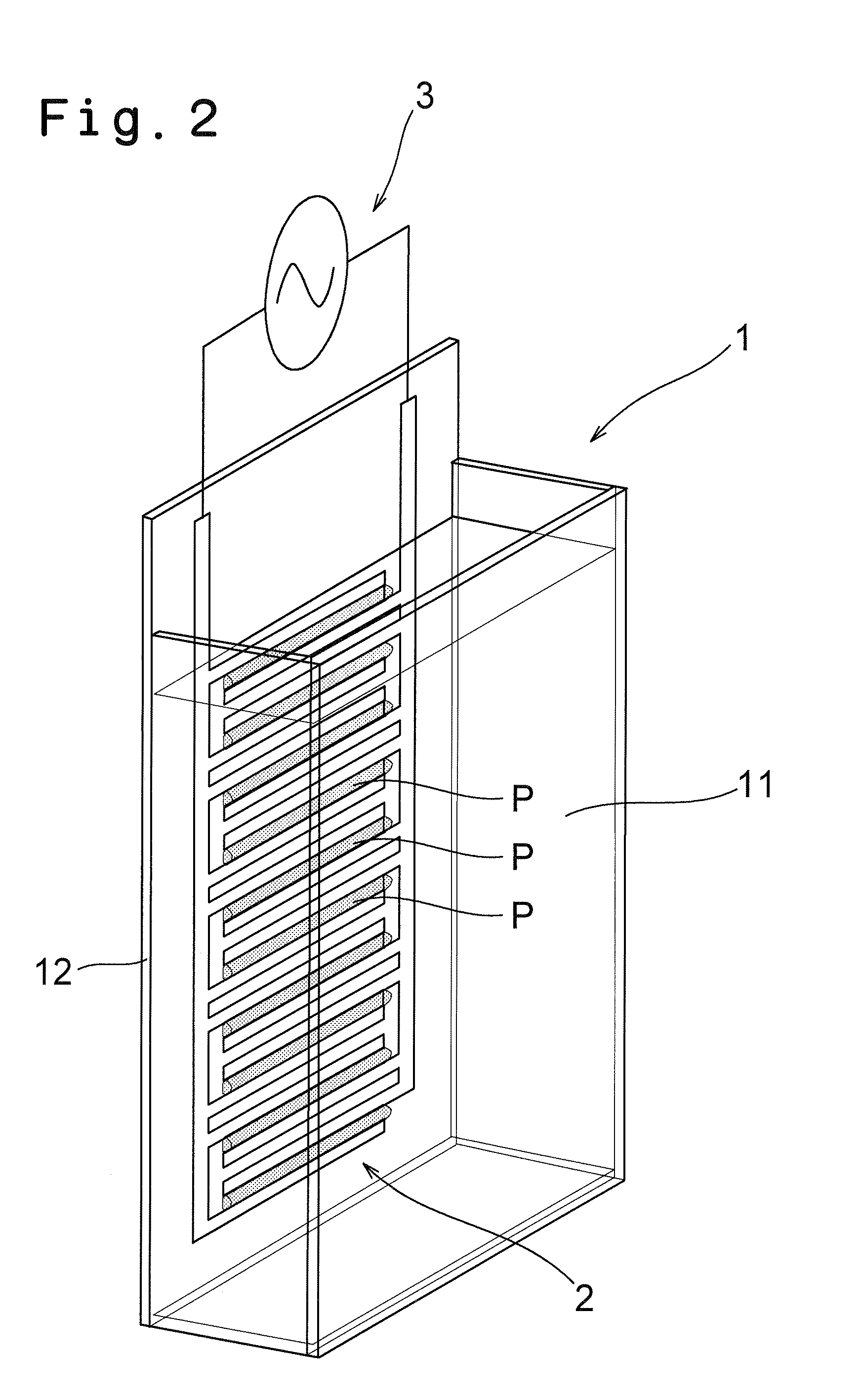
[0045]Hereinafter, preferred embodiments of the present invention will be described in reference to the accompanying drawings. The present invention is never limited by the embodiments as described below, and various embodiments can be of course included therein without departing from the gist of the present invention. Although the migrating force will be described with view of positive migrating force for capturing particles by attraction, negative migrating force having repelling force also similarly functions as a diffraction grating, with a particle density modulation being formed in the vicinity of the electrodes so that the particle density is lower than in the circumference.

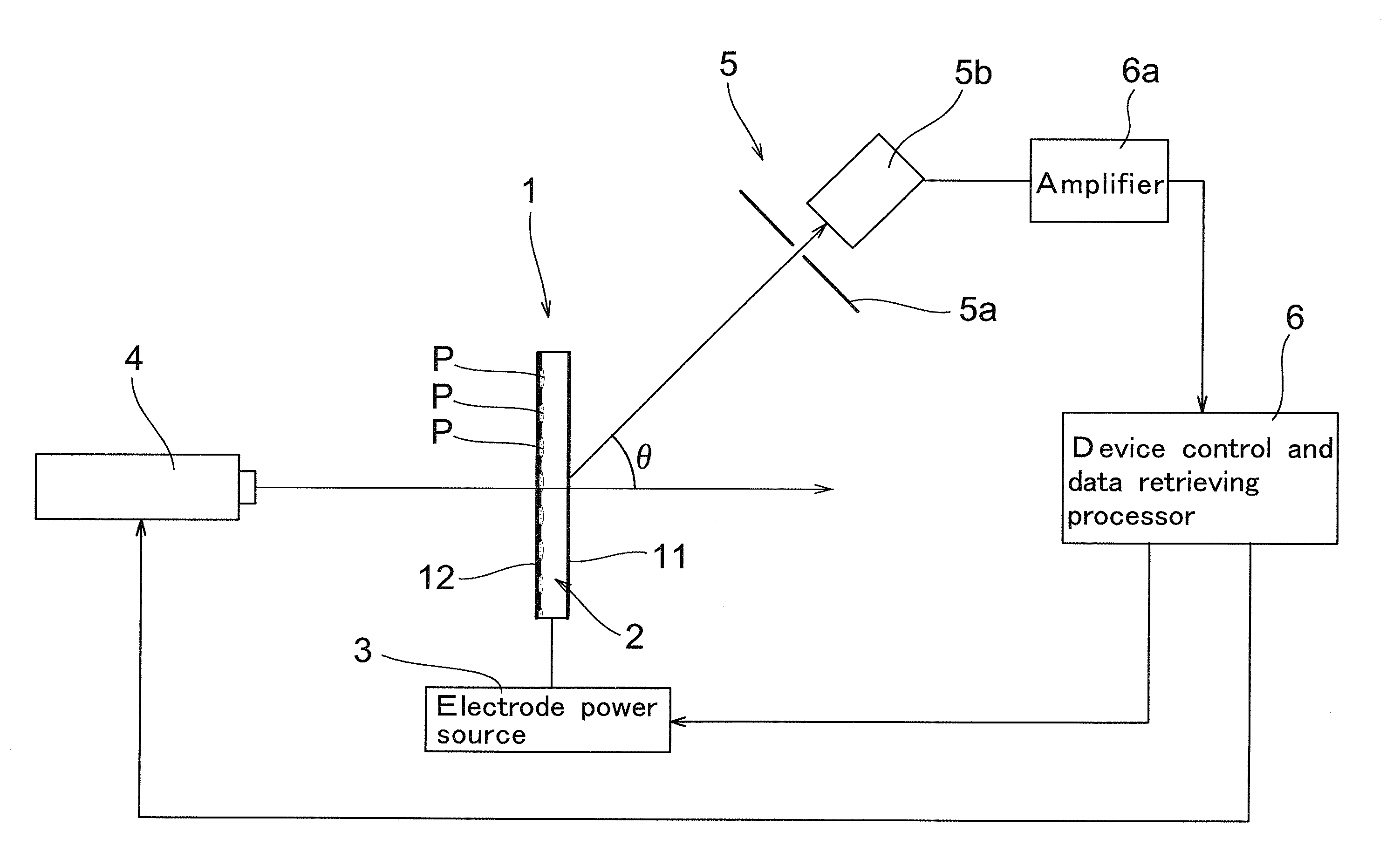
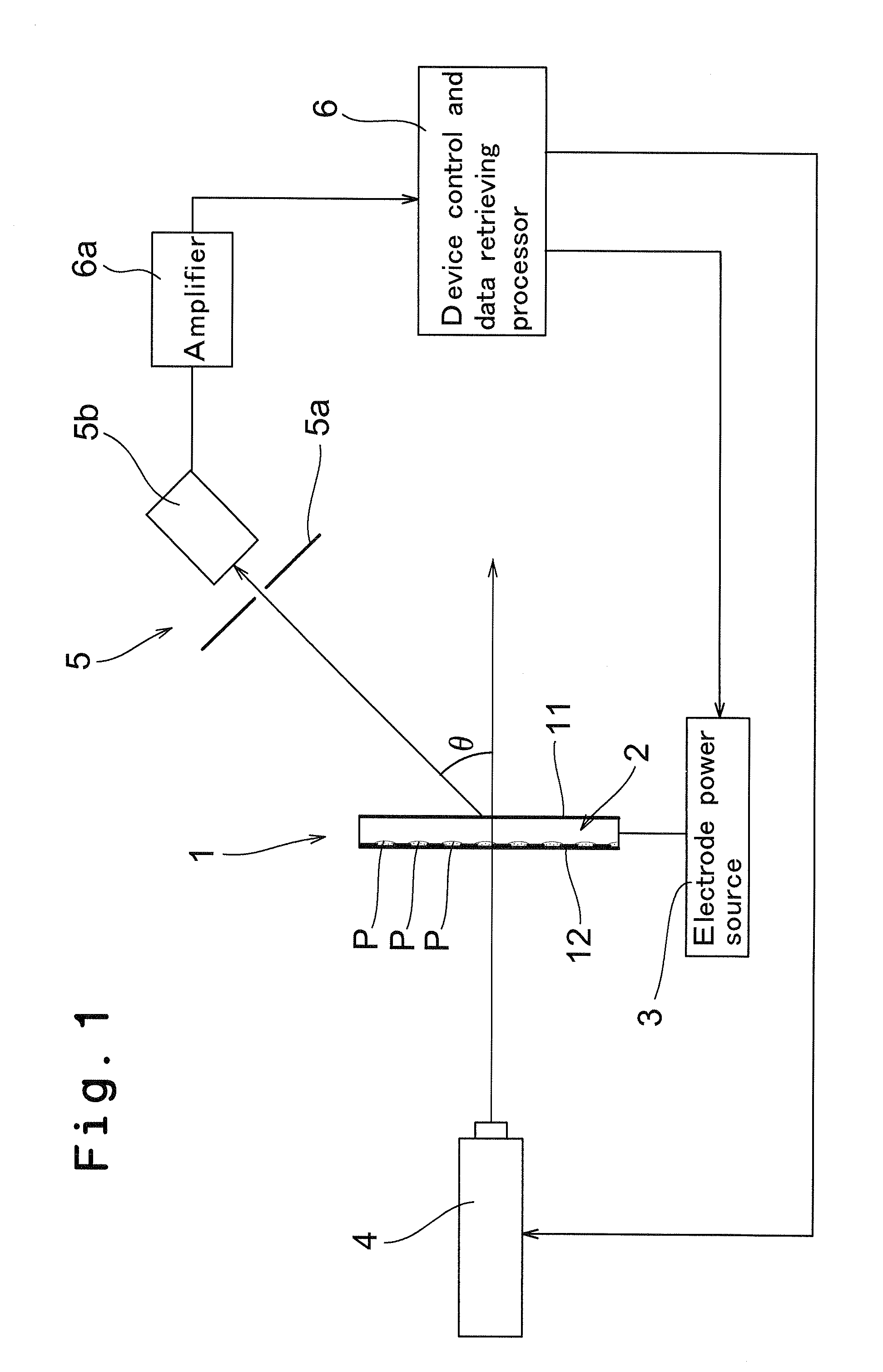
[0046]The apparatus, the whole configuration of which is shown in FIG. 1, includes, as main components, a cell 1 for storing a sample having particles movably dispersed therein, for example, a sample having particles dispersed in a liquid, or a sample composed of a gel having particles movably dispersed th...


PUM

PropertyMeasurementUnit
particle sizeaaaaaaaaaa
sizeaaaaaaaaaa
diameteraaaaaaaaaa

Abstract

A distribution of AC electric field regularly arranged in a cell is formed while storing a sample having particles dispersed in a medium in the cell, whereby the particles are dielectrically migrated in the medium to generate a diffraction grating by density distribution of the particles. Diffracted light generated by irradiating the diffraction grating by density distribution with measuring light is detected, and evaluation of dielectrophoretic intensities of the particles and / or the medium is performed from the detection result. According to this method, evaluation of dielectrophoretic characteristics can be performed without adhering a phosphor to particles, and since even a particle small in size can achieve a detection level by collecting a number of such particles to form a diffraction grating, dielectric characteristics of microparticles of several nanometers in diameter can be thus quantitatively measured with high sensitivity.

Description

FIELD OF THE INVENTION[0001]The present invention relates to a dielectrophoretic intensity evaluation method and apparatus for microparticles including so-called nanoparticles of 100 nm or less in particle size.BACKGROUND OF THE INVENTION[0002]Particles of 100 nm or less in size are generally called nanoparticles, and are just beginning to be used in various fields since they show properties different from those of a general bulk matter composed of the same material. In such a situation, it is becoming important to evaluate the properties of the microparticles.[0003]Dielectrophoresis is known as an evaluation method for microparticle. Dielectrophoresis phenomenon is a phenomenon in which electric polarization is occurred in particles, even if they are charge-free, by applying a strong nonuniform electric field, and the particles are moved due to the attractive force unbalance for polarized positive and negative charges altered by the nonuniform electric field. The intensity of diele...

Claims


Application Information

Patent Timeline
Patent Type & Authority Patents(United States)
IPC IPC(8): B03C5/02
CPCB03C5/005B03C5/026G01N21/4788G01N2015/0003G01N2015/0038
Inventor TSUNAZAWA, YOSHIOWADA, YUKIHISAMORIYA, NAOJITAKUBO, KENJITOTOKI, SHINICHIROSHIMAOKA, HARUO
Owner SHIMADZU CORP
Why Eureka
Try Eureka