Aircraft

a technology for aircraft and wings, applied in the field of aircraft, can solve the problems of significant structural mass and downward twisting of the outer part of the wing, and achieve the effect of reducing the mass of the main plane, increasing the operating speed, size and mass of any conventional central tail plan

Active Publication Date: 2012-12-04
AALTO HAPS LTD
View PDF17 Cites 8 Cited by
  • Summary
  • Abstract
  • Description
  • Claims
  • Application Information

AI Technical Summary

Benefits of technology

[0005]The additional planes of an aircraft according to the invention—which for convenience will be referred to herein as “tip tails”—can act through their connection to the mainplane to provide torsional relief to the latter, particularly in the lower incidence / higher speed case where it is most required and in which the tip tails will be arranged to be in download. In this respect it is well known that positive camber aerofoils such as those useful as the main lifting surface of an aircraft have an inherent pitch down moment, which increases with speed. This causes a tendency for the outer part of the wing to twist downwards and normally requires significant structural mass to cope with these loads, particularly with longer spans and higher speeds. By relieving these loads with the tip tails in accordance with the invention, however, it is possible to reduce the mass of the mainplane and / or to increase operating speed for a given mass. At the same time the presence of the tip tails enables the size and mass of any conventional central tail plane(s) to be reduced while maintaining pitch stability—or to provide all requisite stability in the case of a “flying wing” design where no central tail plane is provided.
[0006]By positioning these tip tails to be subject to the upwash fields of respective vortices from the canted down mainplane tips in accordance with the invention they can themselves be smaller and lighter than if fitted to a mainplane with conventional tips. This is because the tendency of the canted down tips is to place the tip vortices initially further outboard and somewhat lower than a conventional tip. As the vortex sheet wraps up behind the mainplane and moves further inboard, however, the upwash field is located at an optimum position behind each wing for interaction with a trailing tip tail and its effect is concentrated, so adding to the efficiency of the tip tails. Also by virtue of the interaction of the vortex upwash fields with the tip tails the latter can be at a negative angle of physical incidence behind the mainplane and yet have a positive angle of attack with respect to the local relative airflow, particularly in the higher incidence / lower speed cruise condition of the aircraft where general torsional relief for the mainplane is of less importance, thus generating lift with a component in the forward direction of flight and contributing to the thrust requirements of the aircraft.

Problems solved by technology

This causes a tendency for the outer part of the wing to twist downwards and normally requires significant structural mass to cope with these loads, particularly with longer spans and higher speeds.

Method used


Image

  • Aircraft
  • Aircraft

Examples


Embodiment Construction

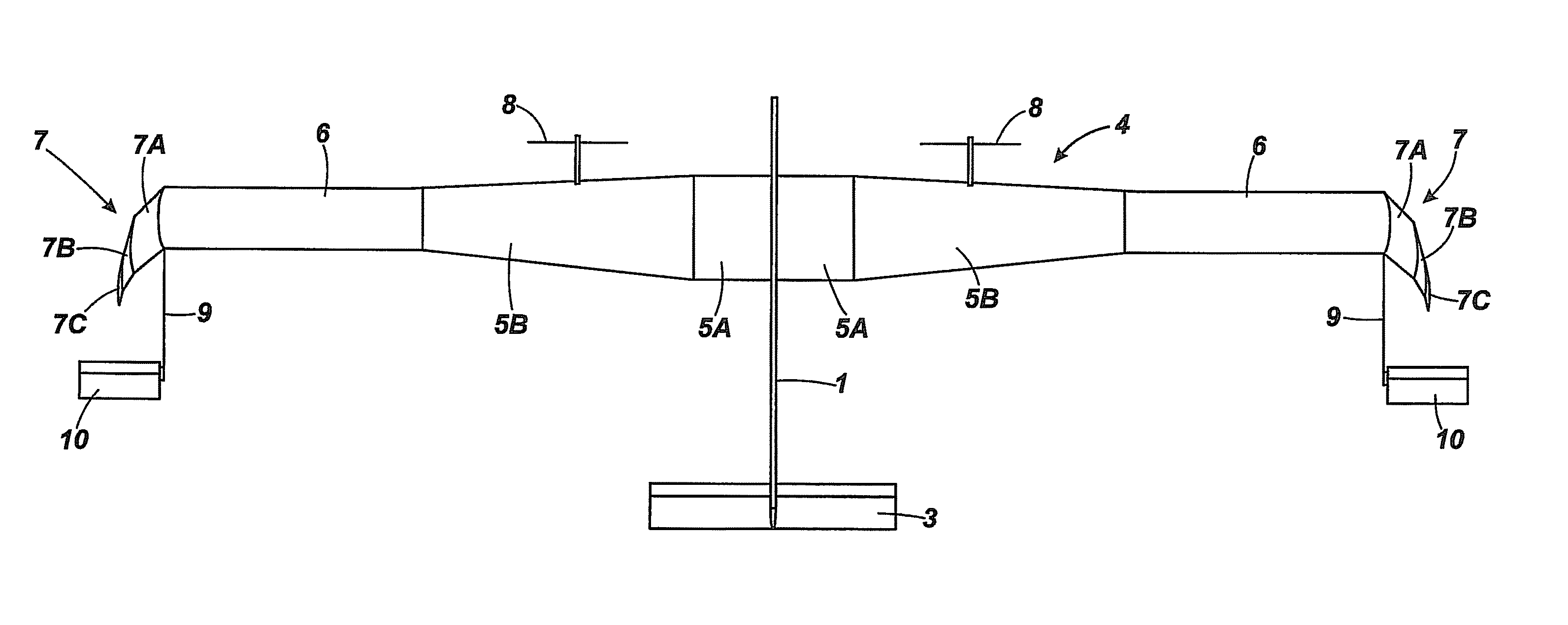
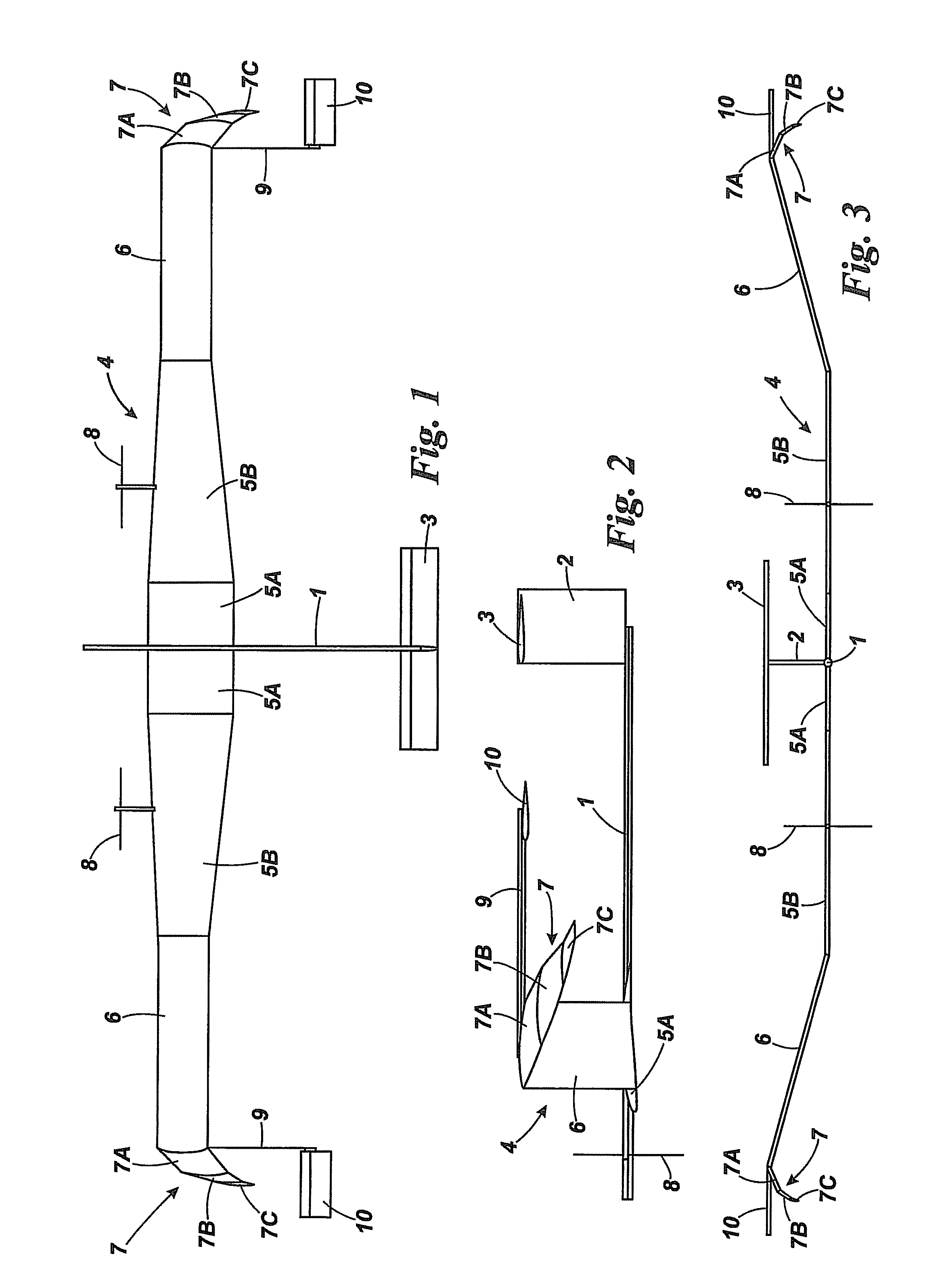
[0011]The aircraft of FIGS. 1 to 3 is a high altitude, long endurance, solar powered UAV. It comprises a tubular fuselage 1 with a tail fin 2 carrying a tailplane 3, and a mainplane 4. Each wing of the mainplane has an inboard portion 5A, 5B, outboard portion 6 and tip 7, as will be described more fully hereinafter. Substantially the whole of the upper surface of each wing portion 5A, 5B and 6 is covered with arrays of photovoltaic cells (not separately shown), or such cells may be housed within the mainplane structure beneath a transparent upper skin. Its powerplant comprises a pair of wing-mounted brushless DC electric motors (not seen) each driving a respective propeller 8, although other embodiments may comprise a different number of such powerplant depending on the size of airframe and motor rating. Housed within the mainplane structure are a plurality of rechargeable lithium ion batteries or regenerative fuel cells.

[0012]In use the UAV will be flown to a desired stratospheric ...


PUM


Abstract

An aircraft, particularly a solar powered, high altitude, long endurance, unmanned aerial vehicle, is equipped with a combination of canted down, raked back wing tips and trailing “tip tails” carried on booms from the tip regions of the mainplane. Each tip tail is positioned to be subject to the upwash field of the respective wing tip vortex, at least in the cruise condition of the aircraft. The wing tip form can achieve a reduction in induced drag and help to relieve wing root bending moment while the tip tails can act through their connections to the mainplane to provide torsional relief to the latter, particularly under lower incidence / higher speed conditions. In the higher incidence / lower speed cruise condition, however, the presence of the tip tails in the upwash fields of the wing tip vortices means that they can generate lift with a component in the forward direction of flight and hence contribute to the thrust requirements of the aircraft.

Description

FIELD OF THE INVENTION[0001]The present invention relates to aircraft and is more particularly (though not exclusively) concerned with high altitude, long endurance, solar powered, unmanned aerial vehicles (UAVs).BACKGROUND OF THE INVENTION[0002]Solar powered UAVs have been proposed for use as long endurance aerial platforms, flying in the generally benign conditions of the stratosphere (typically at altitudes between 15,000 and 30,000 m), for such roles as communications relay, earth observation, weather monitoring, surveillance and mapping. In this respect they may provide a cost-effective alternative to the earth-orbital satellites conventionally used for these purposes and have the additional advantage that they can be easily controlled to remain in sight of a selected part of the globe, by circling or following some other suitable flight pattern, or to fly to any other desired station. Such proposed aircraft typically comprise a lightweight structure including at least a mainpl...

Claims


Application Information

Patent Timeline
Patent Type & Authority Patents(United States)
IPC IPC(8): B64C39/12
CPCB64C23/065B64C39/024B64C2201/021B64C2201/126Y02T50/164B64C23/076B64C23/069Y02T50/10B64U10/25B64U2101/10B64U50/31B64U50/19B64U2101/00
Inventor KELLEHER, CHRISTOPHER CHARLES
Owner AALTO HAPS LTD
Why Eureka
Try Eureka