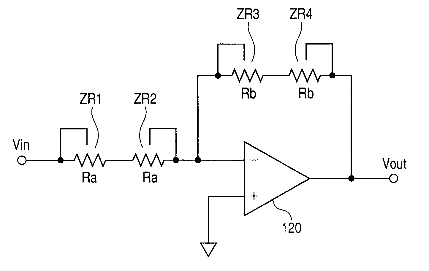
Semiconductor device having resistors with a biased substrate voltage
a technology of resistor elements and semiconductor devices, which is applied in the direction of resistor details, positive-feedback circuit arrangements, transistors, etc., can solve the problems of unstable characteristic of the circuit formed of resistor elements, distortion components that are significant problems, and distortion that occurs in the output signal of the amplifier. to achieve the effect of inhibiting signal distortion
- Summary
- Abstract
- Description
- Claims
- Application Information
AI Technical Summary
Benefits of technology
Problems solved by technology
Method used
Image
Examples
embodiment 1
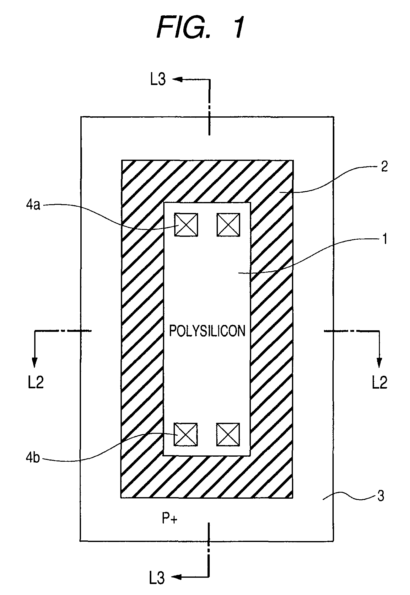
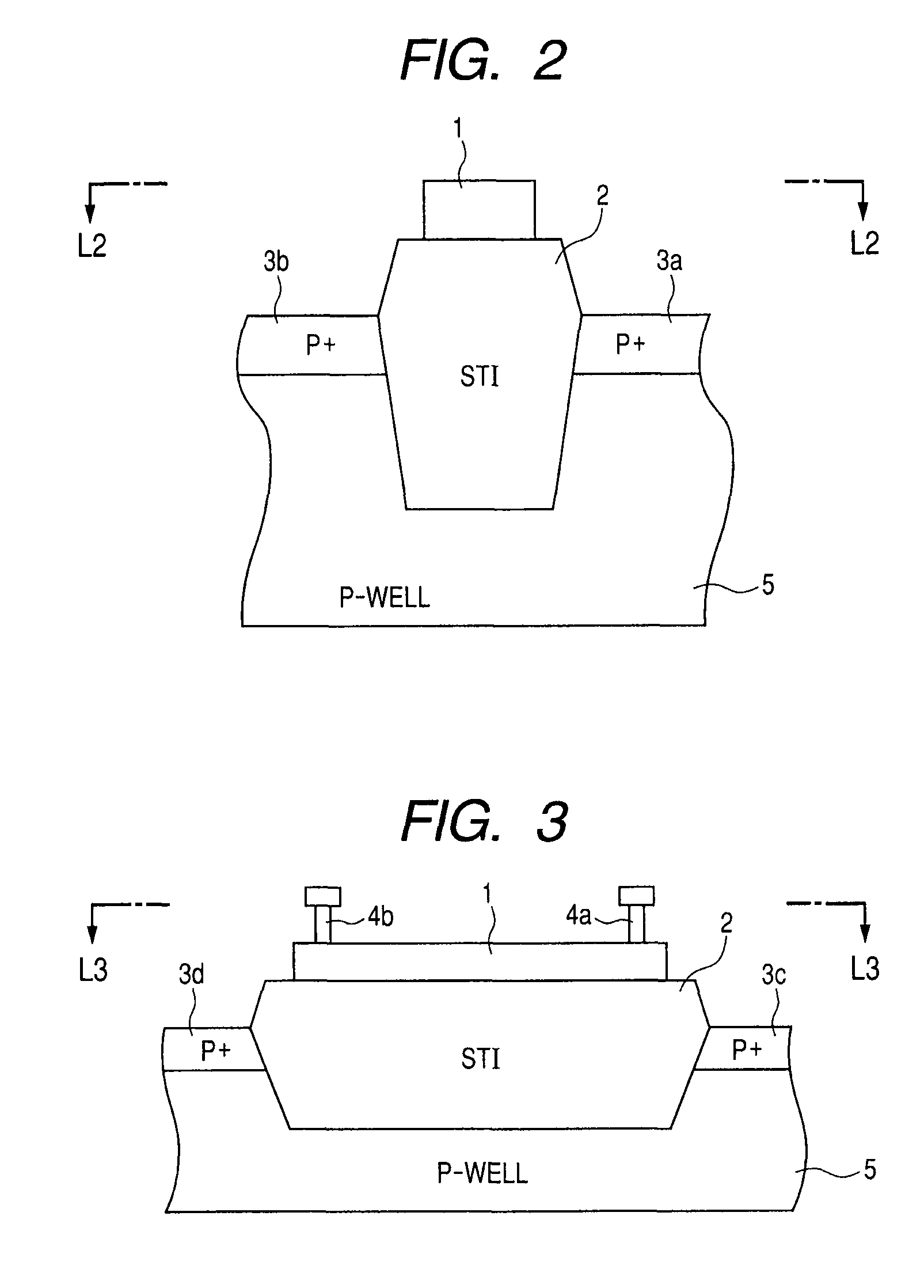
[0060]FIG. 1 is a view schematically showing a two-dimensional layout of a resistor element used in the present invention. In FIG. 1, a polysilicon resistive element 1 having a rectangular shape, and forming the resistor element is disposed over an isolation film 2. The isolation film 2 is, e.g., a shallow trench isolation (STI) film. In a surface of a substrate region (not shown in FIG. 1) around the isolation film 2, there is provided a high-concentration impurity region 3. An example of the high-concentration impurity region 3 is a high-concentration P-type impurity layer in which a P-type impurity has been implanted at a high concentration. Through the high-concentration impurity region 3, a substrate bias voltage is supplied to a well region (substrate region) formed under the high-concentration impurity region 3 (substrate bias voltage for supplying a voltage to a substrate will be described later in detail). The P-type impurity region 3 is used because the polysilicon of the ...
embodiment 2
[0087]FIG. 10 is a view showing the coupling of resistor elements according to Embodiment 2 of the present invention. In FIG. 10, the resistor elements R1 and R2 are coupled in series between the nodes A and C. The coupling node B between the resistor elements R1 and R2 is electrically coupled to the respective substrate regions of the resistor elements R1 and R2. Each of the resistor elements R1 and R2 has the equal resistance value R.
[0088]In a form of substrate voltage supply to the resistor elements R1 and R2 shown in FIG. 10, the average potentials Vx(AB) and Vx(BC) from the respective substrate regions of the resistor elements R1 and R2 are given by the following respective expressions.
[0089]Average Potential from Substrate between nodes A and B: Vx(AB)=(Va+Vb) / 2−Vb=−(−Va+C) / 4. Average Potential from Substrate between nodes B and C: Vx(BC)=(Vb+Vc) / −Vb=(−Va+Vc) / 4. Therefore, in the coupling form of the substrate regions of the resistor elements shown in FIG. 10, the average pot...
embodiment 3
[0098]FIG. 14 is a view schematically showing a two-dimensional layout of resistor elements according to Embodiment 3 of the present invention. In FIG. 14, the resistor elements R1 and R2 are coupled in series between the nodes A and B, and the potential at the coupling node B between the resistor elements R1 and R2 is transmitted to a P-well 45 through a high-concentration impurity region 42, in the same manner as in Embodiment 2. The two-dimensional layout of the resistor elements R1 and R2 is the same as the two-dimensional layout shown in FIG. 12 except that the coupling wires 26A and 26C extend in the longitudinal direction of the drawing. In FIG. 14, the portions of the resistor elements R1 and R2 corresponding to those in the two-dimensional layout shown in FIG. 12 are denoted by the same reference numerals, and a detailed description thereof is omitted.
[0099]In the two-dimensional layout shown in FIG. 14, at locations outside the isolation film 22A, isolation films 42A and 4...
PUM
 Abstract
Description
Claims
Application Information
 - R&D
- Intellectual Property
- Life Sciences
- Materials
- Tech Scout
- Unparalleled Data Quality
- Higher Quality Content
- 60% Fewer Hallucinations
Browse by: Latest US Patents, China's latest patents, Technical Efficacy Thesaurus, Application Domain, Technology Topic, Popular Technical Reports.
© 2025 PatSnap. All rights reserved.Legal|Privacy policy|Modern Slavery Act Transparency Statement|Sitemap|About US| Contact US: help@patsnap.com


