
Implantable cerebrospinal fluid flow device and method of controlling flow of cerebrospinal fluid

a technology of cerebrospinal fluid and flow control, which is applied in the field of implantable cerebrospinal fluid flow control devices and methods, can solve the problems of slit ventricles, slit ventricles, neurological damage, etc., and achieve the effect of reducing the effect of intracranial pressure pulsation, reducing the resistance to flow, and improving the expected function of shunts

Active Publication Date: 2012-12-18
MEDTRONIC PS MEDICAL
View PDF25 Cites 5 Cited by
  • Summary
  • Abstract
  • Description
  • Claims
  • Application Information

AI Technical Summary

Benefits of technology

[0009]The invention provides an implantable shunt system that includes one or more catheters and a fluid control device that utilizes the properties of the catheters to improve the expected function of the shunt by providing a higher or lower resistance to the flow through the shunt and reducing the effect of pulsations of intracranial pressure on the shunt system.

Problems solved by technology

However, if blockages exist in the circulation pathways of cerebrospinal fluid, perhaps in the ventricles, cerebrospinal fluid can't be reabsorbed by the body at the proper rate.
If left untreated, the increased intracranial pressure can lead to neurological damage and may result in death.
A common complication for these implanted shunt systems is over-drainage, potentially resulting in slit ventricles, slit ventricle syndrome, loss of brain compliance, shunt occlusion, sub-dural hematoma or any of a number of other complications.
Over-drainage may still occur with the use of these valves due to significant intracranial pressure spikes.
Shunt valves are also prone to clogging.
A clogged shunt valve could result in serious complications through failure to provide proper drainage of cerebrospinal fluid from the ventricles of the brain.

Method used


Image

  • Implantable cerebrospinal fluid flow device and method of controlling flow of cerebrospinal fluid
  • Implantable cerebrospinal fluid flow device and method of controlling flow of cerebrospinal fluid
  • Implantable cerebrospinal fluid flow device and method of controlling flow of cerebrospinal fluid

Examples


Embodiment Construction

[0020]The entire content of U.S. Patent Application Ser. No. 60 / 741,118, filed Dec. 1, 2005, is hereby incorporated by reference.

[0021]Consistent and reliable drainage of cerebrospinal fluid from one area of the body to another, e.g., from a ventricle or ventricles of the brain to another region of the body such as the peritoneum or sagittal sinus, can be desirable. A consistent and reliable drainage method and system can minimize the expense as well as trauma and inconvenience to the patient associated with cerebrospinal fluid shunt revision surgery and can also lessen risk to the patient due to an inoperative cerebrospinal fluid drainage system.

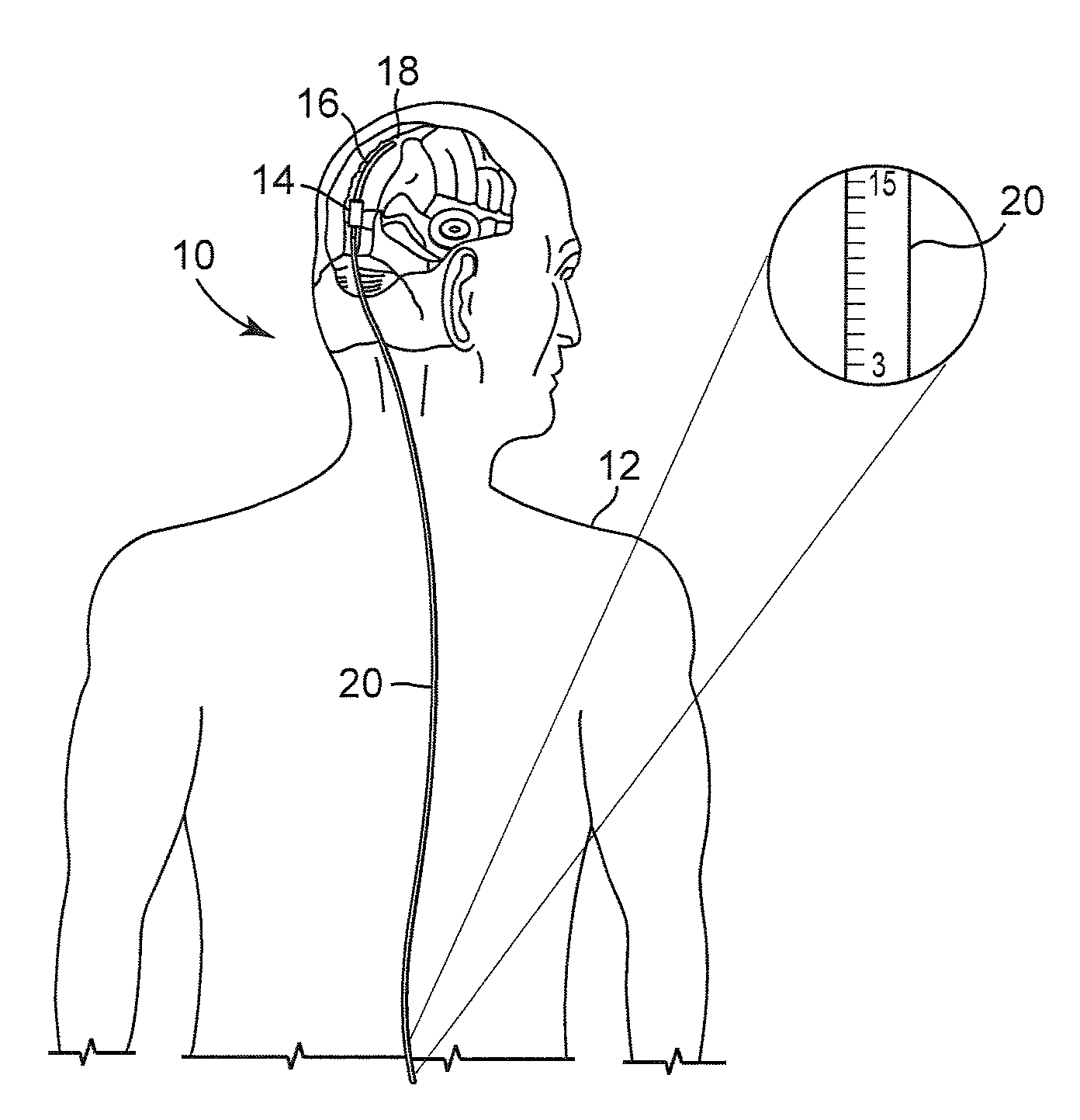
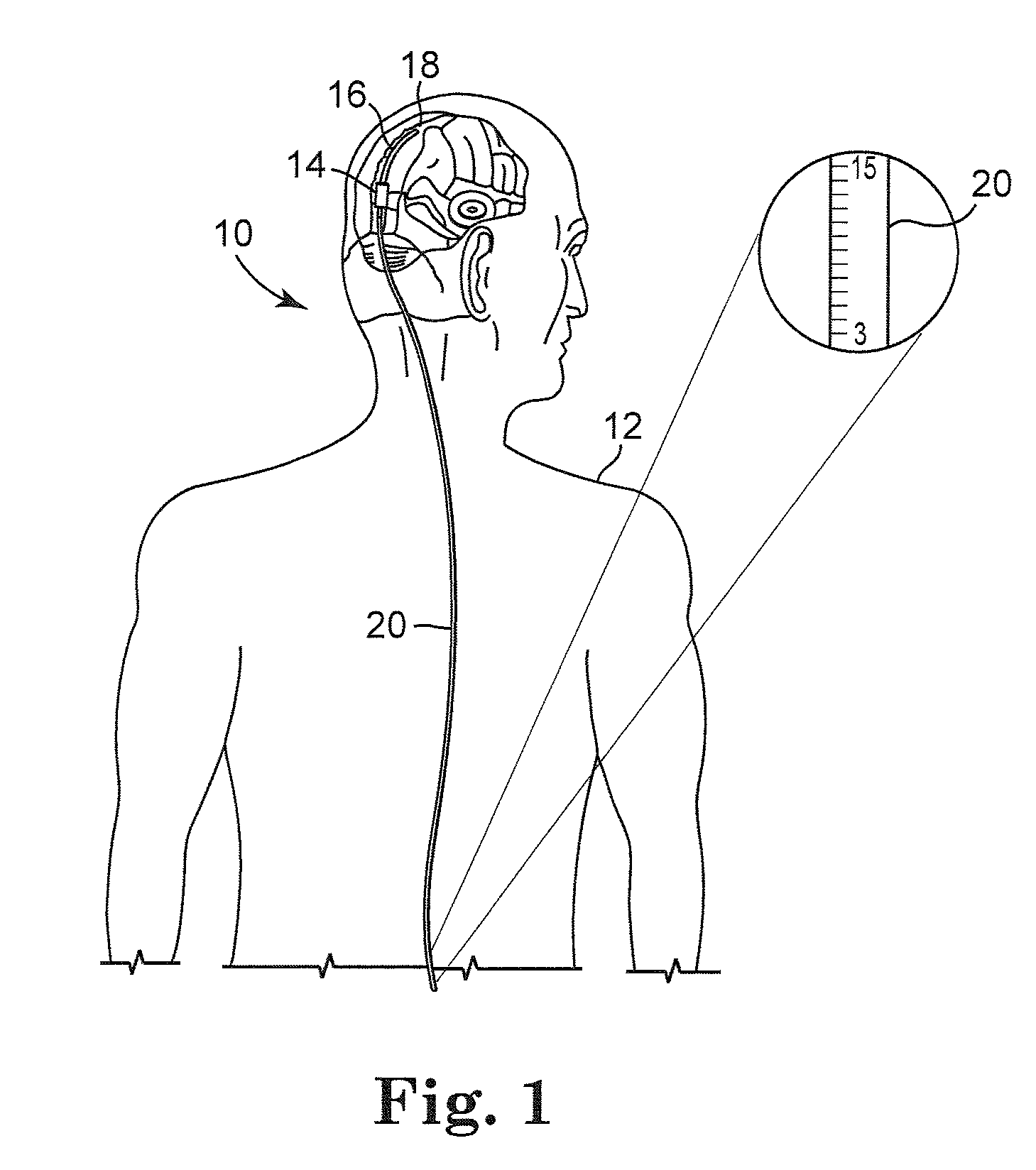
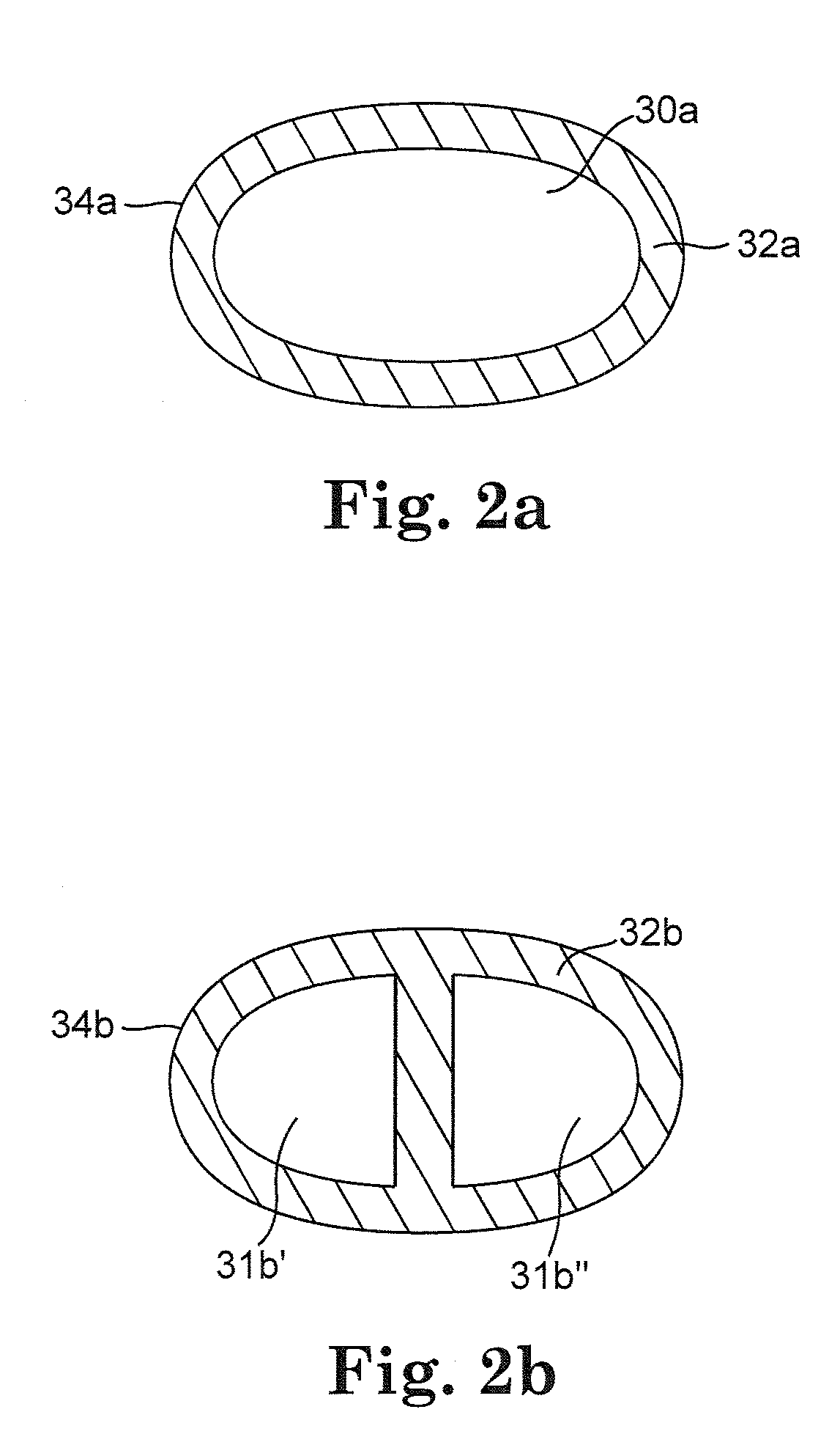
[0022]FIG. 1 illustrates an embodiment of a cerebrospinal fluid shunt 10 for draining cerebrospinal fluid from one area, for example the ventricles of the brain, of the body of patient 12 to another area of the body of patient 12. In one embodiment cerebrospinal fluid can be drained to the peritoneum, the right atrium, the sagittal sinus, o...


PUM


Abstract

An implantable shunt that includes one or more catheters configured so that the implantable shunt has a resistance to flow greater than about 3 mm Hg / mL / minute. An implantable shunt system that includes one or more catheters and a fluid control device that utilizes the properties of the catheters to improve the expected function of the shunt by providing a higher or lower resistance to the flow through the shunt and reduces the effect of pulsations of cerebrospinal fluid on the shunt system.

Description

RELATED APPLICATION[0001]This application is related to and claims priority from U.S. Patent Application Ser. No. 60 / 741,118, filed Dec. 1, 2005.FIELD[0002]This invention relates generally to implantable fluid flow control devices and methods and, more particularly, to such devices and methods for controlling flow of cerebrospinal fluid.BACKGROUND[0003]Ventricles of the brain contain cerebrospinal fluid which cushions the brain against shock and provides a means for nutrient and waste transport in the brain. Cerebrospinal fluid is constantly being secreted and absorbed by the body, usually in equilibrium. Cerebrospinal fluid is produced in the ventricles of the brain, where under normal conditions, it is circulated in the subarachnoid space and reabsorbed into the bloodstream, predominantly into the superior sagittal sinus via the arachnoid villi. However, if blockages exist in the circulation pathways of cerebrospinal fluid, perhaps in the ventricles, cerebrospinal fluid can't be r...

Claims


Application Information

Patent Timeline
IPC IPC(8): A61M5/00A61M39/00A61M29/00A61M25/00A61M25/14A61F2/02A61F2/04A61F2/82
CPCA61M27/006
Inventor BERTRAND, WILLIAM J.SPECKMAN, LORI C.REVELES, JAVIER J.KIEHL, ANDY R.
Owner MEDTRONIC PS MEDICAL
Learn More