Method for the quantitative determination of the concentration of fluorophores of a substance in a sample and apparatus for carrying out the same

a technology of fluorophores and quantitative determination, which is applied in the direction of spectrum investigation, calibration apparatus, color/spectral properties measurement, etc., can solve the problem of insufficient long-term stability of this kind of fluorescence standard, and achieve the effect of reducing the excitation light source and simple construction

Inactive Publication Date: 2012-12-18
LRE RELAIS & ELECTRONICS GMBH
View PDF23 Cites 10 Cited by
  • Summary
  • Abstract
  • Description
  • Claims
  • Application Information

AI Technical Summary

Benefits of technology

[0021]It is also advantageous to use the optical element as a standard of comparison for the calibration of the detected second measured value, whereby in particular contamination, temperature effects and / or deterioration effects of elements of a measuring apparatus for carrying out the method can be compensated with the help of the standard of comparison.
[0022]Moreover it is advantageous for the optical path between the reference light source and the optical element used for coupling in the constant portion of the reference light emitted by the reference light source in the direction of the receiving element to pass through the same optical elements as the optical path of the excitation light between the excitation light source and the sample or between the excitation light source and the fluorescence standard, respectively. In this way an arrangement for carrying out the method can have a simple construction. Also, changes in the properties of the optical elements in the optical path affect both the reference light and the excitation light. Alternatively within the optical path of the excitation light an additional filter may be arranged whose transmission range is centered about the excitation wave length. This filter is not positioned within the optical path of the reference light between the reference light source and the optical element.
[0023]Moreover it is advantageous to direct the optical paths of the excitation light and of the reference light onto the optical element under different angles. This enables a simple construction of an apparatus for carrying out the method. In particular the space required for arranging the reference light source and the excitation light source is reduced.
[0038]An apparatus for carrying out the method preferably includes a carrier for a sample to be measured, an emission branch comprising an excitation light source for emitting excitation light of an excitation wave length, a first receiving element for measuring the intensity of the excitation light and a first filter arranged within the path of the excitation light, the transmission range of which filter is centered about the excitation wave length, as well as a receiving branch comprising a second receiving element for measuring the intensity of the fluorescent light of an emission wave length coming from the sample, and a second filter whose transmission range is centered about the emission wave length. In this arrangement, a reference light source for emitting at least one reference beam of the emission wave length is arranged within the emission branch. The first receiving element serves to measure the intensity of the light of both light sources of the emission branch. In the apparatus an optical element is arranged so that it receives the light of the reference light source of the emission branch. With such a relatively simple configuration of the apparatus the number of fluorophores of a sample can be detected within a detection zone in a simple manner while changes in the properties of the apparatus can be compensated based on the reference measuring with the help of the optical element. The emission branch and the receiving branch are preferably combined to form an optical module which can be adjusted relative to the optical element and to the sample carrier. Moreover it is advantageous to arrange the first receiving element between the first filter and the sample carrier or between the first filter and the optical element, respectively.
[0041]In the method according to the invention thus a calibration can be carried out with the help of an optical element or of a reflectance standard which can be produced with the desired long-term stability. It is sufficient to carry out a single adjustment of this optical element with the help of an adjusted fluorescence standard during a starting-up calibration of a measuring apparatus for carrying out the method. Subsequently the fluorescence density of a sample can always be determined with reference to a deposited internal optical element or reflectance standard. The starting-up calibration is for example carried out at the place of manufacture of the measuring apparatus before delivering the measuring apparatus to the customer or alternately during a start-up or reconnection of the measuring apparatus at the location of the customer or user. The aim of such a starting-up calibration is in particular to minimize a variation of the measuring results between several produced measuring apparatus and / or to enable traceability of the measuring results of a measuring apparatus to an authoritative standard with long-term stability or to a collective of several measuring apparatus. When tracing the measuring results of a measuring apparatus back to a collective of several measuring apparatus, the measuring results of all measuring apparatus of the collective can be compared to each other in a simple manner.

Problems solved by technology

However the long-term stability of this kind of fluorescence standards is usually insufficient.

Method used


Image

  • Method for the quantitative determination of the concentration of fluorophores of a substance in a sample and apparatus for carrying out the same
  • Method for the quantitative determination of the concentration of fluorophores of a substance in a sample and apparatus for carrying out the same
  • Method for the quantitative determination of the concentration of fluorophores of a substance in a sample and apparatus for carrying out the same

Examples


Embodiment Construction

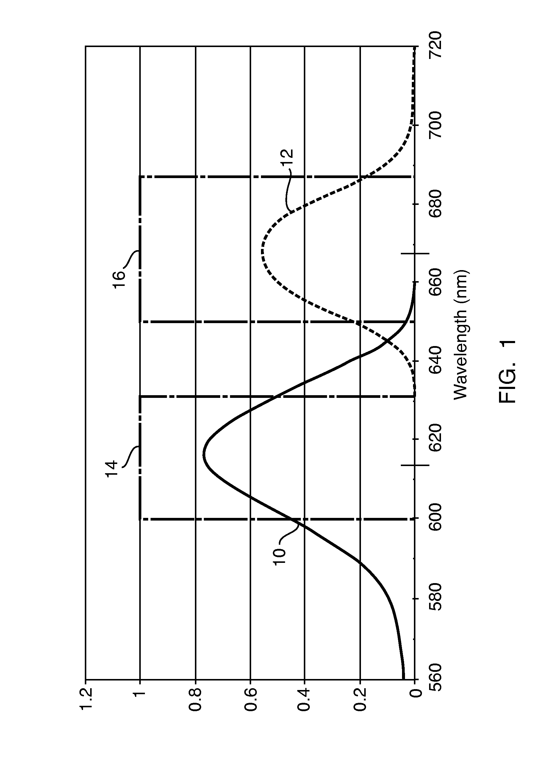
[0050]FIG. 1 shows the gradient of efficiency of the excitation light with reference to the wave length by means of a graph 10, as well as the emission characteristic of the corresponding fluorescent light by means of a graph 12. Moreover, a rectangle 14 represents the filter characteristic of the excitation branch or emission branch, while the rectangle 16 represents the filter characteristic of a receiving or measuring branch. When the Stokes shift is small, as shown in FIG. 1, interference filter with very steep edges are preferably used as filters 14 and 16. The interference filters for the excitation branch are preferably dimensioned such that maximum excitation efficiency is reached and the wave length of the excitation light source is within the transmission range of the filter.

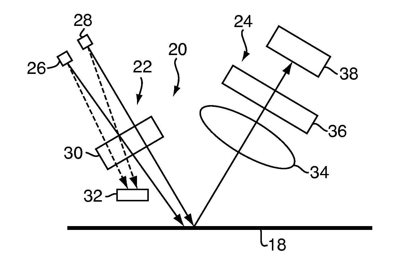
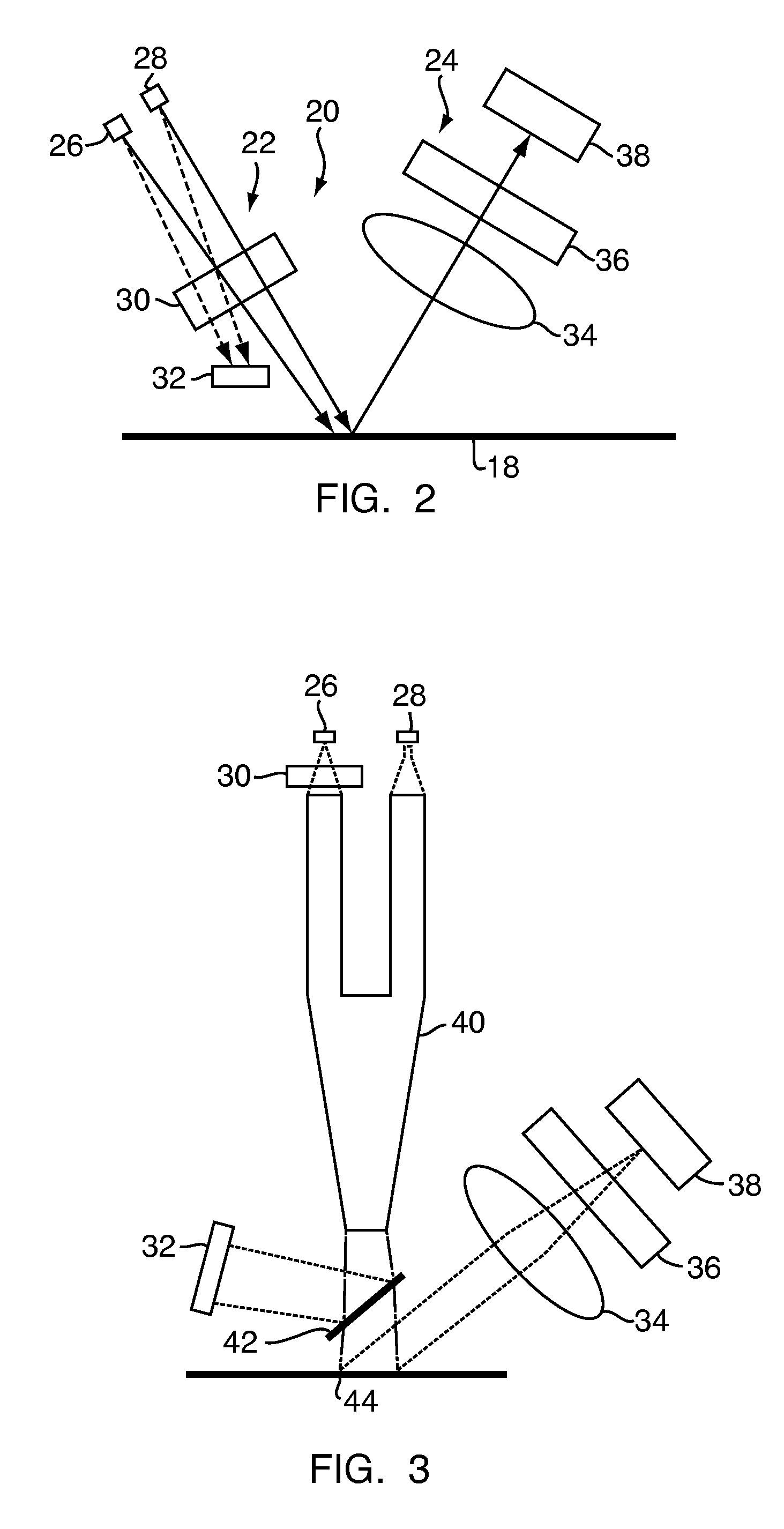
[0051]In the embodiment of FIG. 2, reference number 18 denotes schematically a carrier for a sample to be measured or a reflectance standard, respectively. Above this plane 18 an optical module, genera...


PUM


Abstract

The invention concerns methods and apparatuses for quantitatively determining the concentration of fluorophores of a substance in a sample. A constant portion of the reference light of a reference light wave length (λr) emitted by a reference light source is coupled in by an optical element in the direction of a receiving element. A first value corresponding to the portion of the reference light coupled in which is incident on the receiving element is detected. The sample is irradiated with the excitation light of an excitation wave length (λex) emitted by an excitation light source. A second value corresponding to the portion of the fluorescent light of an emission wave length (λem) emitted by the sample which is incident on the receiving element. The ratio of the second value to the first value is determined. The number of fluorophores in the substance is determined based on the ratio.

Description

CROSS REFERENCE TO RELATED APPLICATION[0001]This application claims the benefit of German Application No. 102008057115.6, filed Nov. 13, 2008, the disclosure of which is herein incorporated by reference in its entirety.FIELD OF THE INVENTION[0002]The invention concerns a method for the quantitative determination of the concentration of fluorophores of at least one substance in a sample, wherein this substance is irradiated with light of an excitation wave length emitted by an excitation light source and the intensity of the fluorescent light of an emission wave length coming from the sample is measured by means of a receiving element.BACKGROUND OF THE INVENTION[0003]Normally a so-called fluorescence standard is used for calibrating a measured intensity value of the fluorescent light, which standard emits fluorescent light of a known wave length distribution and intensity when irradiated with excitation light of a preset wave length and intensity. However the long-term stability of t...

Claims


Application Information

Patent Timeline
Patent Type & Authority Patents(United States)
IPC IPC(8): F21V9/16G01J1/58G01T1/10G21H3/02G21K5/00H01J65/06H01J65/08
CPCG01N21/278G01N21/6428
Inventor EGGER, RAFAEL
Owner LRE RELAIS & ELECTRONICS GMBH
Why Eureka
Try Eureka