Method for joining ceramic components

a technology of ceramic components and components, applied in the field of ceramics, can solve the problems of difficult to manufacture using conventional ceramic fabrication techniques, difficult to meet the requirements of engineering designs for many applications, and difficult to meet the requirements of manufacturing, etc., to achieve the effect of improving thermal properties, improving strength, and reducing shrinkag

Active Publication Date: 2013-01-08
COORSTEK INC
View PDF17 Cites 4 Cited by
  • Summary
  • Abstract
  • Description
  • Claims
  • Application Information

AI Technical Summary

Benefits of technology

[0010]The present invention has been developed in response to the present state of the art, and in particular, in response to the problems and needs in the art that have not yet been fully solved by currently available techniques for joining ceramic components. Accordingly, a method has been developed to produce a bond that provides improved strength, in some cases equal to or greater than the ceramic components it binds together, while also providing improved matching of thermal properties (e.g., CTE). Further disclosed is a method for producing a bond that is stable at high temperatures, begins bonding at room temperature, and exhibits minimal shrinkage.

Problems solved by technology

Nevertheless, engineering designs for many applications require fabricating parts with relatively complex shapes and geometries.
Many of these shapes may be quite expensive and in some cases impossible to manufacture using conventional ceramic fabrication techniques.
For example, as illustrated in FIG. 1, a simple U-shaped tube 100 may be very difficult to produce using conventional ceramic fabrication techniques, such as slip casting, tape casting, injection molding, dry pressing, or the like.
Many of these adhesives, however, may combust and degrade when subjected to temperatures exceeding 200° C. Other inorganic ceramic binders have been developed that can withstand temperatures of 1600° C. or more.
Many of these binders, however, do not provide the strength needed for many applications.

Method used


Image

  • Method for joining ceramic components
  • Method for joining ceramic components
  • Method for joining ceramic components

Examples


example 1

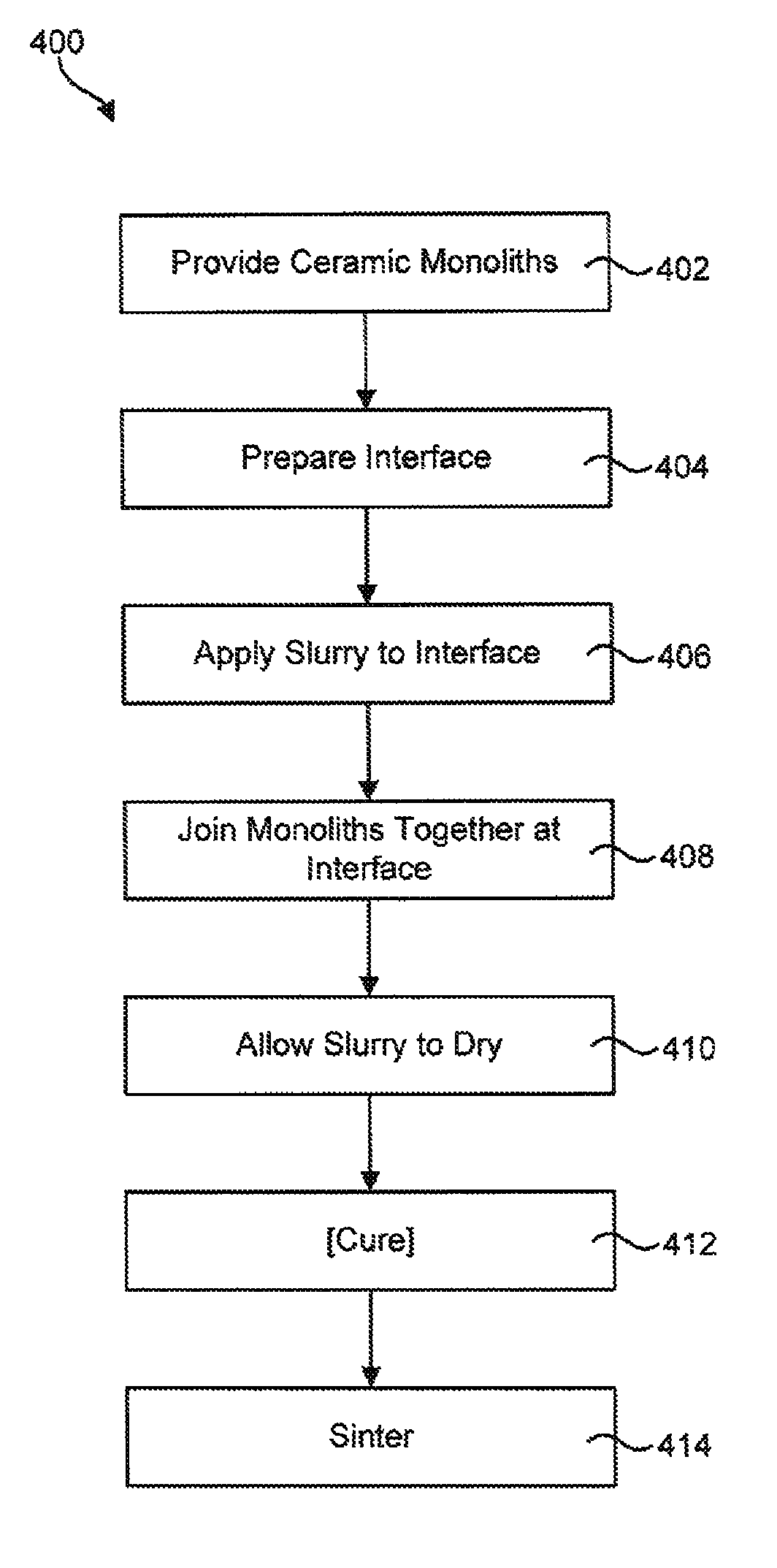
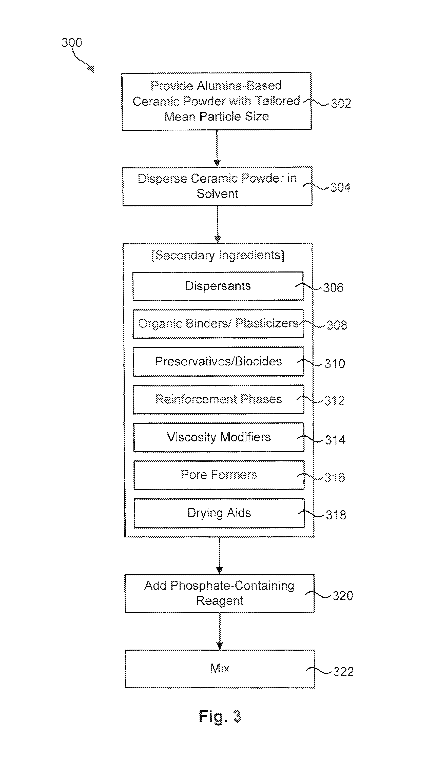
[0051]A slip, containing the reactants alumina powder and phosphoric acid, among other constituents, may be produced using the process described in association with FIG. 3. Two ceramic components may be fabricated by pouring the slip into a mold. The slip may then be dried at room temperature to provide a pair of green ceramic components. The slip may then be applied to one or more mating surfaces of the green components. While the slip is still wet, the components may be joined together at their mating surfaces. Pressure may or may not be applied to the joint. The joint may then be allowed to dry and the entire assembly may be fired at a temperature between about 250° C. and 1600° C. to harden and densify the ceramic components and the joint.

[0052]Two green ceramic components were joined using the process described in the previous paragraph and fired at a temperature of approximately 900° C. The slip contained alumina powder having a mean particle size between 1 and 5 microns. The ...

example 2

[0053]A slip, containing the reactants alumina powder and phosphoric acid, among other constituents, may be produced using the process described in association with FIG. 3. Two ceramic components may be fabricated by pouring the slip into a mold. The slip may then be cured at a temperature between about 40° C. and 250° C. until the ceramic components are semi-hard. The hardness may be increased by increasing the curing temperature. The slip may then be applied to one or more mating surfaces of the pre-cured components. If desired, the mating surfaces may be polished or roughened prior to applying the slip. While the slip is still wet, the components may be joined together at their mating surfaces. Pressure may or may not be applied to the joint. The joint between the cured ceramic components may then be allowed to dry and the entire assembly may be fired at a temperature between about 250° C. and 1600° C.

[0054]Two ceramic components pre-cured at 220° C. were joined using the process...

example 3

[0055]A slip, containing the reactants alumina powder and phosphoric acid, among other constituents, may be produced using the process described in association with FIG. 3. Two ceramic components may be fabricated by pouring the slip into a mold. The slip may then be fired at a temperature between about 250° C. and 1400° C. until the ceramic components are hard and strong. Their hardness and strength may be increased by increasing the firing temperature. The slip may then be applied to one or more mating surfaces of the fired components. If desired, the mating surfaces may be polished or roughened prior to applying the slip. While the slip is still wet, the components may be joined together at their mating surfaces. Pressure may or may not be applied to the joint. The joint may then be allowed to dry and the entire assembly may be fired at a temperature between about 250° C. and 1600° C.

[0056]Two ceramic components, pre-fired at 1300° C., were joined using the process described in t...


PUM

PropertyMeasurementUnit
particle sizeaaaaaaaaaa
temperatureaaaaaaaaaa

Abstract

A method for joining multiple ceramic components together is disclosed in one embodiment of the invention as including providing multiple ceramic components, each having a mating surface. A slip containing a mixture of alumina powder and a phosphate-containing reagent is applied to one or more of the mating surfaces. The mean particle size of the alumina powder is tailored to provide improved strength to the bond. Once the slip is applied, the ceramic components may be joined together at their mating surfaces. The joint may then be sintered to react the constituents in the mixture and thereby generate a bond between the ceramic components.

Description

RELATED APPLICATIONS[0001]This application is a continuation-in-part of U.S. patent application Ser. No. 11 / 464,476 filed on Aug. 14, 2006, now U.S. Pat. No. 7,628,951, and entitled PROCESS FOR MAKING CERAMIC INSULATION.BACKGROUND OF THE INVENTION[0002]1. Field of the Invention[0003]The present invention relates to ceramics and more particularly to methods for joining ceramic components.[0004]2. Description of the Related Art[0005]Advanced ceramics and fiber-reinforced ceramic matrix composites with characteristics such as high strength, toughness, good thermal conductivity, thermal shock resistance, and oxidation resistance are needed for many applications. The properties of many ceramic materials, such as hardness, stiffness, heat-resistance, corrosion resistance, low density, and low cost, make these materials highly desirable for many applications, including aeronautical, automotive, military, communications, medical, consumer, and computer applications, to name just a few.[0006...

Claims


Application Information

Patent Timeline
Patent Type & Authority Patents(United States)
IPC IPC(8): B29C65/00C03B29/00C04B37/00
CPCC04B35/6269C04B35/6309C04B37/005C04B2235/447Y10T156/10C04B2235/656C04B2235/96C04B2237/064C04B2237/343C04B2235/5436
Inventor AKASH, AKASHNAIR, BALAKRISHNAN G.
Owner COORSTEK INC
Why Eureka
Try Eureka