Reactor system and process for the catalytic polymerization of olefins, and the use of such reactor system in catalytic polymerization of olefins

a technology of catalytic polymerization and reactor system, which is applied in the direction of furnaces, furnace types, lighting and heating apparatus, etc., can solve the problems of increasing the risk of reactor interruption or plugging, and achieve the effects of low gas velocity, high reaction rate, and good control

Inactive Publication Date: 2013-01-15
BOREALIS TECH OY
View PDF39 Cites 26 Cited by
  • Summary
  • Abstract
  • Description
  • Claims
  • Application Information

AI Technical Summary

Benefits of technology

[0028]The present invention has for its object to provide means having a good control of the outflow rate of polymer particles from the moving bed unit into the fluidized bed unit while the inflow of fluidization gas from the fluidized bed unit into the moving bed unit via the outlet of the moving bed unit is substantially avoided. This is true because the low gas velocity and the high reaction rate will increase the risk of a reactor interruption or plugging. Still there will be substantially no interference with the optimal functioning of the moving bed unit and of the fluidized bed unit.

Problems solved by technology

This is true because the low gas velocity and the high reaction rate will increase the risk of a reactor interruption or plugging.

Method used


Image

  • Reactor system and process for the catalytic polymerization of olefins, and the use of such reactor system in catalytic polymerization of olefins
  • Reactor system and process for the catalytic polymerization of olefins, and the use of such reactor system in catalytic polymerization of olefins
  • Reactor system and process for the catalytic polymerization of olefins, and the use of such reactor system in catalytic polymerization of olefins

Examples


example 1

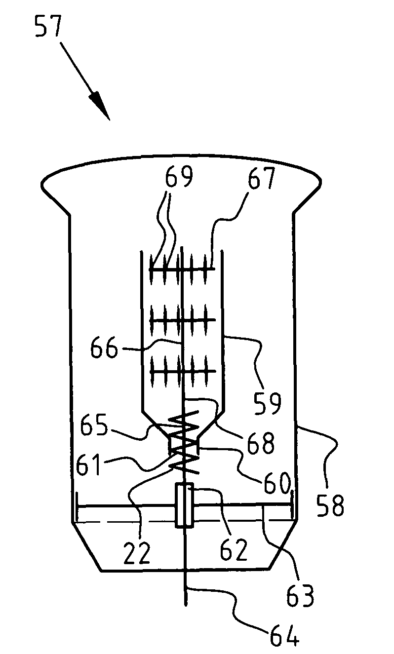
[0077]The fluidized bed reactor was used as described in FIG. 3. The screw was horizontal orientated and has an 80 mm compression zone at the outlet of the moving bed unit. The horizontal screw comprised four screw elements having a thickness of 7 mm, a diameter of 154 mm and a flight length of 82 mm.

[0078]A bed of polyethylene powder having an average diameter (as determined by sieving) of 300 μm was used with air as fluidization gas. The flow rate of air was 135 kg / h and the temperature was 25° C. The bed level was 146 cm. The flow rate of the powder within the moving bed unit was set by adjusting the screw speed, which was done by adjusting the frequency of the 1 kW motor of the screw.

[0079]The frequency of the screw motor was set to 20 Hz. Metered amounts of polymer particles were displaced out of the moving bed unit. This caused a powder flow within the moving bed to be 2.3 dm3 / s and consequently the powder residence time in the moving bed unit was 37 s

example 2

[0080]The procedure of Example 1 was repeated except that frequency was set to 15 Hz. The powder flow within the moving bed was then 1.7 dm3 / s and the powder residence time 52 s.

example 3

[0081]The procedure of Example 1 was repeated except that frequency was set to 10 Hz and the air flow to 103 kg / h. The powder flow within the moving bed was then 1.1 dm3 / s and the powder residence time 80 s.


PUM

PropertyMeasurementUnit
pressureaaaaaaaaaa
temperatureaaaaaaaaaa
pressureaaaaaaaaaa

Abstract

The invention relates to a reactor system and process for the catalytic polymerization of olefin monomer and optionally comonomer(s), having one or more inlets for olefin monomer, catalyst, optionally for comonomer, chain growth controllers or chain transfer agents, and/or inert gas, an outlet for gas and an outlet for polymerized particles. The reactor system has at least one fluidized bed unit and at least one moving bed unit, wherein the fluidized bed unit has means for maintaining a fluidized bed in the fluidized bed unit and wherein the moving bed unit is provided with an inlet and an outlet which are connected to the fluidized bed unit, wherein the outlet of the moving bed unit is provided with means for displacing metered quantities of polymerized particles from the moving bed unit into the fluidized bed unit, and to the use of such reactor system.

Description

BACKGROUND OF THE INVENTION[0001]1) Field of the Invention[0002]The present invention relates to a reactor system and to a process for the catalytic polymerization of olefins, and to the use of such reactor system for catalytic polymerization of olefins.[0003]2) Description of Related Art[0004]The catalytic polymerization of olefins uses among others a catalyst of the Ziegler-Natta type. New generations of catalyst for olefin polymerization including single site catalysts have been developed in view of a more regular polymer structure. During the catalytic polymerization the olefin composition is substantially constant around the particle.[0005]Polyolefins produced using a recent generation of Ziegler-Natta catalysts have a relative narrow molecular weight distribution. The breadth of the molecular weight distribution influences the rheology behaviour and the final mechanical properties of the produced polyolefins.[0006]In order to obtain a broader multimodal molecular weight distri...

Claims


Application Information

Patent Timeline
Patent Type & Authority Patents(United States)
IPC IPC(8): C08F2/34B01J8/24C08F10/02
CPCB01J8/082B01J8/10B01J8/12B01J8/1809B01J8/386B01J8/388C08F10/00C08F2/38C08F2/34B01J2208/00256B01J2208/00274B01J2208/00557C08F2500/24
Inventor BERGSTRA, MICHIELERIKSSON, ERIKWEICKERT, GUNTER
Owner BOREALIS TECH OY
Why Eureka
Try Eureka