
Method and arrangement for measuring the distance to an object

a distance measurement and object technology, applied in distance measurement, height/levelling measurement, instruments, etc., can solve the problems of preventing battery-powered systems from being used, severely limited maximum achievable demodulation frequency, and large amount of power dissipation

Active Publication Date: 2013-01-15
ECOLE POLYTECHNIQUE FEDERALE DE LAUSANNE (EPFL)
View PDF13 Cites 97 Cited by
  • Summary
  • Abstract
  • Description
  • Claims
  • Application Information

AI Technical Summary

Benefits of technology

This solution enables low-power, cost-effective, and high-resolution distance measurement without the drawbacks of existing technologies, facilitating integration on a single chip and reducing the need for complex optical elements, thus being suitable for battery-powered and high-volume applications.

Problems solved by technology

Since the charge carrier transport mechanism of most CCDs and photogates is based on a thermal diffusion process rather than on a drift effect, the maximum achievable demodulation frequency is severely limited.
Since CCD gates are essentially metal-oxide-semiconductor (MOS) or semiconductor-oxide-semiconductor (SOS) capacitors, this type of image sensor dissipates a large amount of power, thus preventing them to be used in battery-powered systems.
The requirement of an external companion chip is an additional drawback in standard CCD fabrication technology.
Nevertheless, since conventional photodiodes fabricated in a standard CMOS process are inferior to CCD photodiodes in terms of sensitivity and noise, this technique may require more powerful illumination source for the same depth of accuracy, or limits the signal to noise ratio (SNR) for a given illumination power budget, if compared to the technique of the above references relating to CCD.
Beside, most of the above drawbacks of CCD technologies still persist.
In addition, the generation of such high power and precise light pulse could potentially increase the overall cost of such system.
Nevertheless, both techniques require very fast laser diodes (DL) to generate pulses with sub-nanosecond duration.
These requirements on special optical elements can potentially increase the overall cost of systems based on this principle, thus potentially preventing them to be used in high-volume applications.

Method used


Image

  • Method and arrangement for measuring the distance to an object
  • Method and arrangement for measuring the distance to an object
  • Method and arrangement for measuring the distance to an object

Examples


Embodiment Construction

[0051]The present invention proposes a realization method of a solid-state rangefinder imager sensor comprising avalanche photodiodes (APD), and a continuous-modulated illumination scheme.

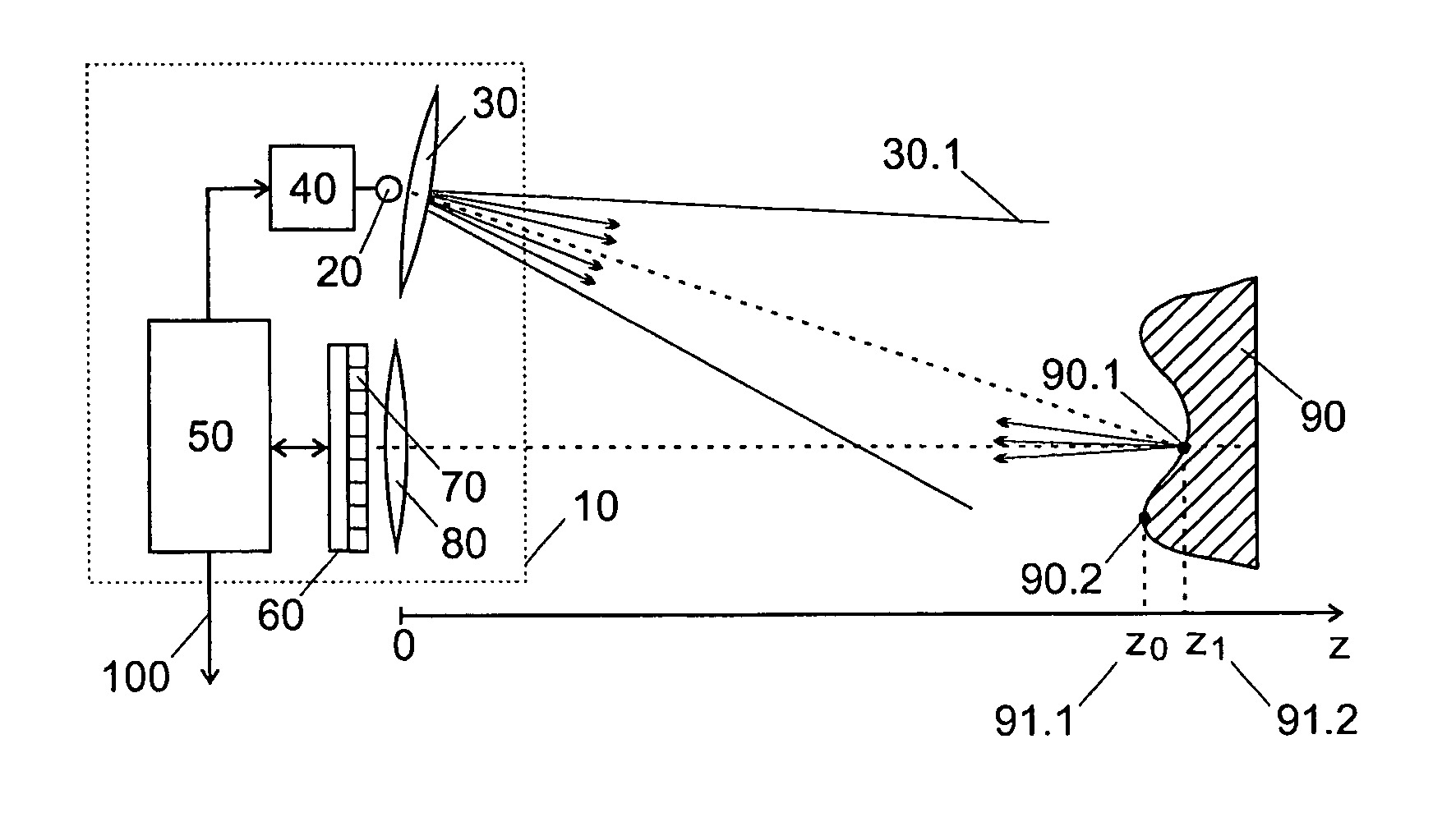
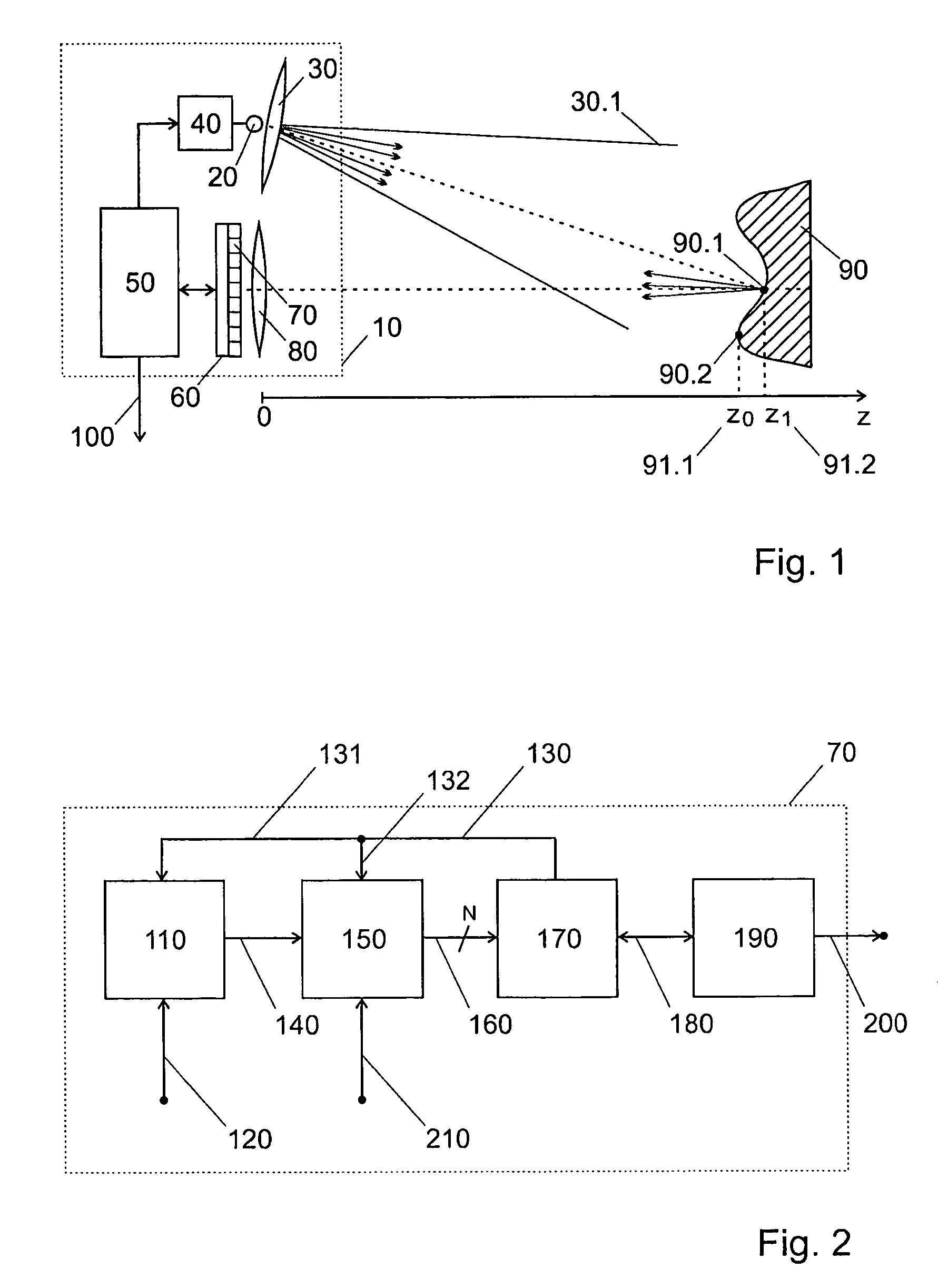
[0052]FIG. 1 illustrates an example of realization of an arrangement according to the present invention. The arrangement 10 includes a light source 20, light source optics 30 used to create a cone of light 30.1, a light source driver 40, a controller 50, a solid-state image sensor 60 comprising an array of pixels 70 based on avalanche photodiodes and an imaging lens 80. The light source 20, based for example on an array of LEDs or DLs, emits a periodic continuous modulated optical signal with frequency F and duty cycle close to 50%. The light source optics, usually an optical diffuser and / or a lens, creates a cone of light 30.1 that illuminates an object 90 in the scene. Different points of the object, such as 90.1 and 90.2, are imaged on different pixels on the imager sensor 60 by means of an imag...


PUM


Abstract

Arrangement (10) for measuring the distance to an object, comprising:a photonic source for illuminating said object using a continuous modulated photonic wave,a solid-state image sensor, comprising an array of avalanche photodiodes and a plurality of circuits for processing signals output by said avalanche photodiodes to yield data depending on the photonic wave reflected by said object onto said photodiodes.The circuit may comprise a multiplexer at the pixel level arranged so as to accumulate the signal output by the avalanche photodiode during different sub-periods in different storage devices.

Description

REFERENCE DATA[0001]This application claims priority of U.S. provisional patent application No. US60 / 752027 filed on Dec. 21, 2005, the contents whereof are hereby incorporated.FIELD OF THE INVENTION[0002]The present invention concerns the field of integrated circuits. In particular, it concerns a new technique for a solid-state image sensor based on avalanche photodiodes that measures the distance of objects in addition to their intensity image.DESCRIPTION OF RELATED ART[0003]Systems based on solid-state electronic circuits that measure the distance from a reference to an object are known in the art. Examples of such systems not based on stereoscopy and interferometry use can be divided into two main principles: triangulation and time-of-flight (TOF). Systems based on triangulation evaluate depth by illuminating a tiny spot of the scene with a laser ray. The distance of that spot to the sensor is determined by the known angle of incidence of the reflected light.[0004]For example, S...

Claims


Application Information

Patent Timeline
Patent Type & Authority Patents(United States)
IPC IPC(8): G01C3/08
CPCG01C3/08G01S7/491G01S7/493G01S17/36G01S17/89G01S17/894
Inventor NICLASS, CRISTIANO
Owner ECOLE POLYTECHNIQUE FEDERALE DE LAUSANNE (EPFL)
Learn More