Device for applying and monitoring medical atherectomy

a technology for atherectomy and catheters, applied in the field of devices for carrying out and monitoring atherectomy, can solve the problems of significant risk for patients, inability of medical personnel to distinguish between plaque and artery wall, perforation of artery, etc., and achieve the effect of reducing the number of method steps and the number of catheters used, eliminating plaque, and high detail resolution of structures

a technology for atherectomy and catheters, applied in the field of devices for carrying out and monitoring atherectomy, can solve the problems of significant risk for patients, inability of medical personnel to distinguish between plaque and artery wall, perforation of artery, etc., and achieve the effect of reducing the number of method steps and the number of catheters used, eliminating plaque, and high detail resolution of structures

US8359086B2Inactive Publication Date: 2013-01-22SIEMENS HEALTHCARE GMBH

Image

  • Device for applying and monitoring medical atherectomy
  • Device for applying and monitoring medical atherectomy

Examples


Embodiment Construction

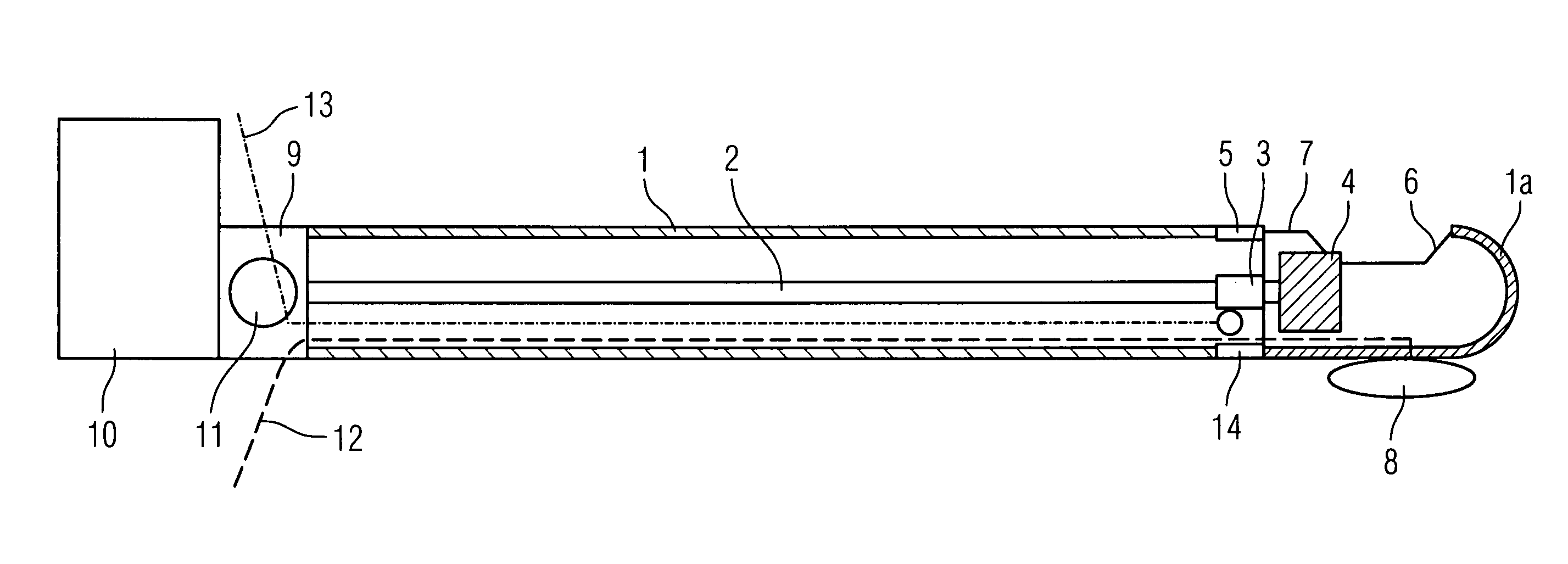
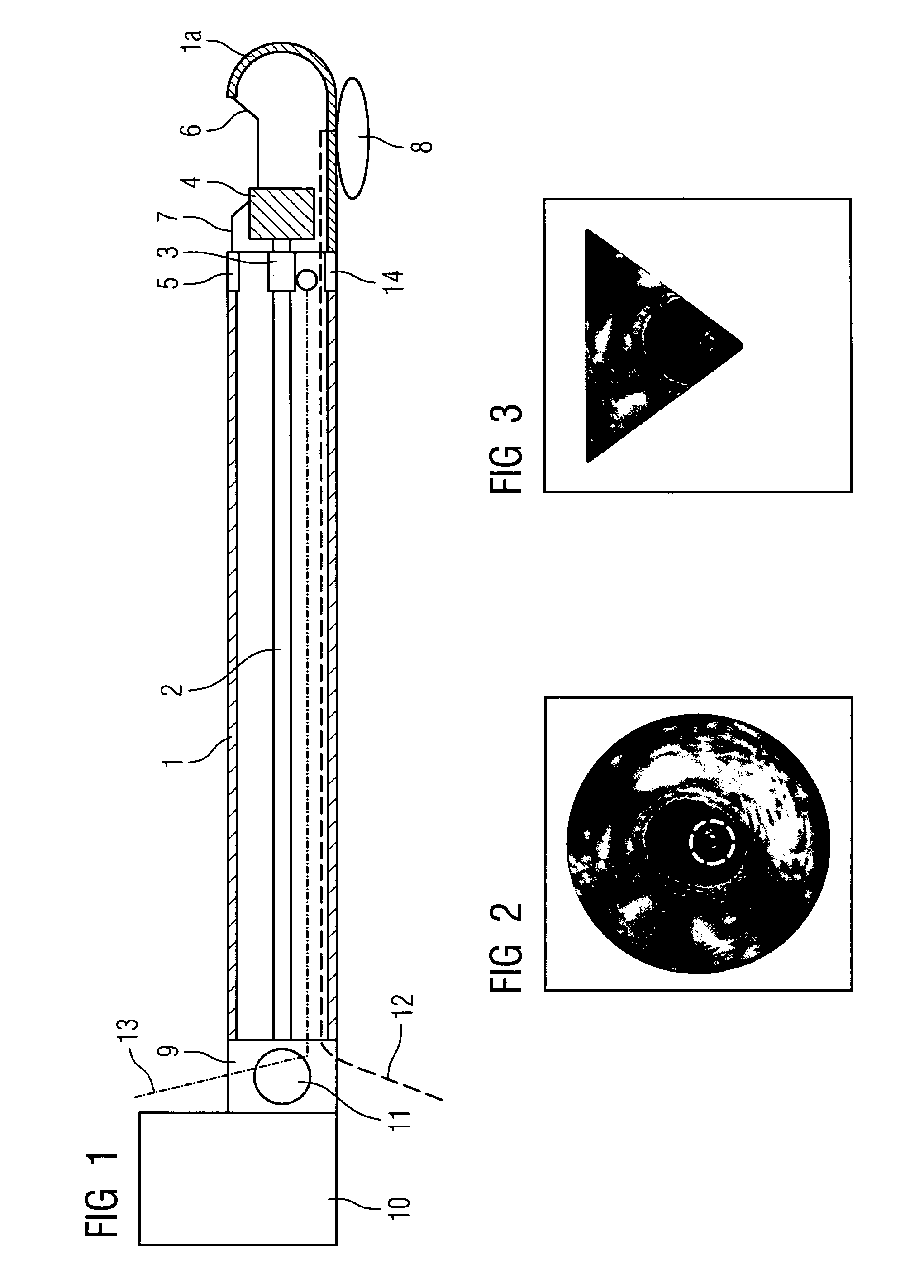
[0022]FIG. 1 shows a schematic diagram of a combined atherectomy-OCT catheter with an external flexible catheter casing 1 with a rigid catheter tip1a. A hollow flexible drive shaft 2 with a glass-fiber line (not shown) running through it as the OCT line is arranged within the catheter casing. The hollow flexible drive shaft 2 serves both to drive a rotatable mirror forming the OCT sensor 3, which in the exemplary embodiment shown—viewed from the external end of the catheter out—is in front of the knife 4. The OCT sensor 3 lies within a revolving ring-shaped window 5, while the rotating knife 4 also driven by the drive shaft 2 passing through it projects into the window opening 6 of the rigid catheter tip 1a. The knife with its blade is therefore somewhat set back compared with the external contour 7 of the catheter tip 1a.

[0023]An inflatable balloon 8 on the side of the catheter tip 1a opposite the window opening 6 can press said catheter tip onto the inner wall of the artery, so t...


PUM


Abstract

Device for carrying out and monitoring an atherectomy, with which a cutting knife driven in a rotating manner by an external unit and set back to project into an opening in the tip of the catheter can be pressed onto the artery wall by means of an inflatable balloon arranged on the side of the catheter casing opposite the window opening, an atherectomy catheter being connected to an OCT catheter to form an integrated unit.

Description

CROSS REFERENCE TO RELATED APPLICATIONS[0001]This application claims priority to the German application No. 10 2004 008 371.1, filed Feb. 20, 2004 which is incorporated by reference herein in its entirety.FIELD OF INVENTION[0002]The invention relates to a device for carrying out and monitoring an atherectomy, with which a cutting knife driven in a rotating manner by an external unit set back to project into an opening in the tip of the catheter can be pressed onto the artery wall by means of an inflatable balloon arranged on the side of the catheter casing opposite the window opening.BACKGROUND OF INVENTION[0003]One of the most common fatal diseases is vascular disease, in particular cardiac infarct. This is caused by disease of the coronary arteries (arteriosclerosis). With this disease deposits (arteriosclerotic plaque) cause a “blockage” of the coronary arteries.[0004]If coronary angiography shows serious narrowing (stenosis) of the coronary arteries, which causes angina pectoris...

Claims


Application Information

Patent Timeline
22 Jan 2013
Publication
US8359086B2
IPC
A61B17/00; A61B1/04; A61B5/00; A61B17/22; A61B17/32; A61B19/00; A61M25/16
CPC
A61B5/0066; A61B5/0084; A61B5/6852; A61B17/3207; A61B17/320783; A61B1/042; A61B19/5244; A61B2019/5231
Inventors
MASCHKE, MICHAEL