

Porous carbon structure, method for preparing same, electrode catalyst for fuel cell, and electrode and membrane-electrode assembly including same
a technology of porous carbon and catalyst, which is applied in the direction of cell components, physical/chemical process catalysts, and sustainable manufacturing/processing. it can solve the problems of difficult to increase the specific surface area of a carbon material having similar size pores, and difficult to synthesize porous carbon materials. achieve the effect of improving electronic conductivity and specific surface area
- Summary
- Abstract
- Description
- Claims
- Application Information
AI Technical Summary
Benefits of technology
Problems solved by technology
Method used
Image

Examples
example 1
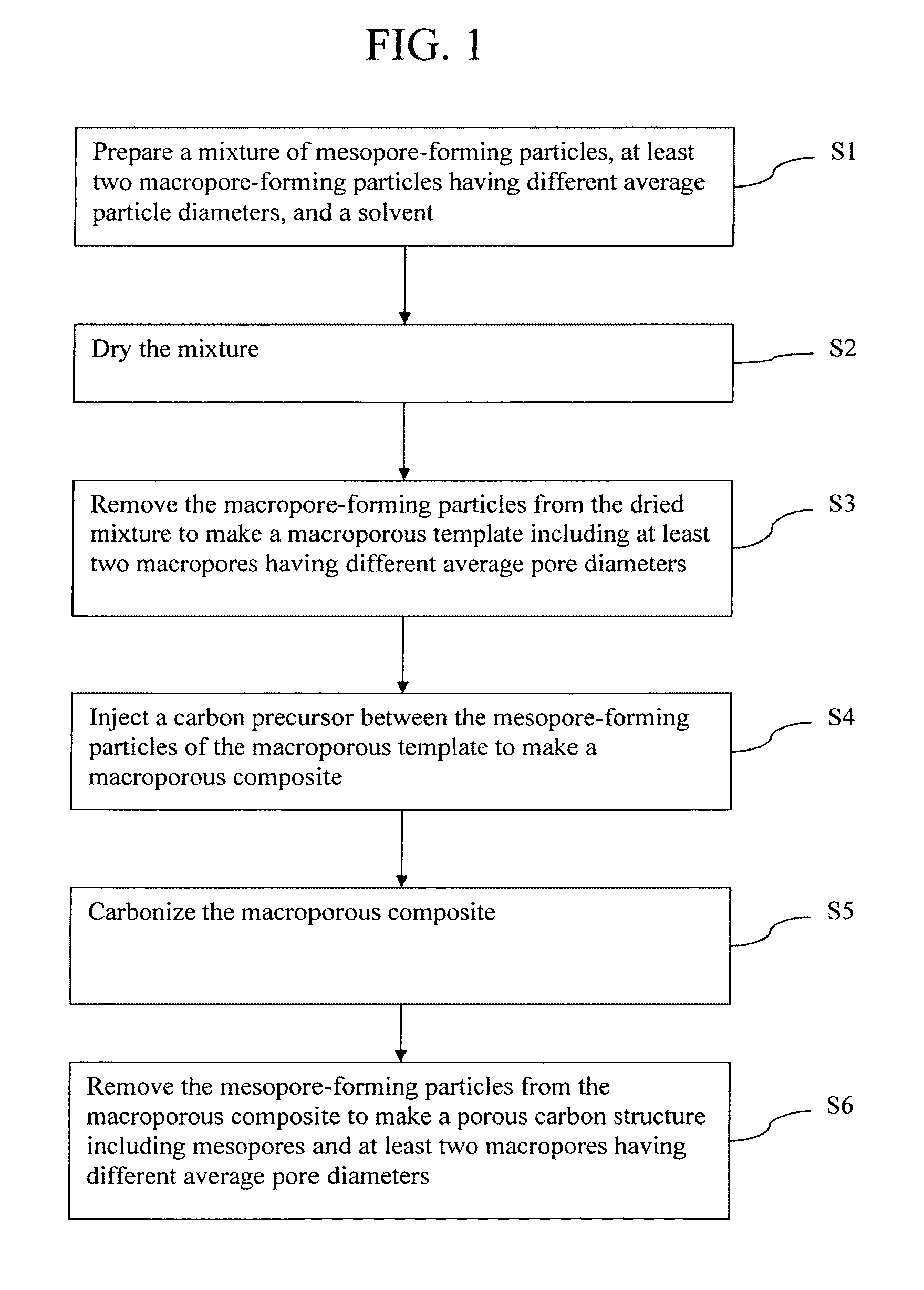
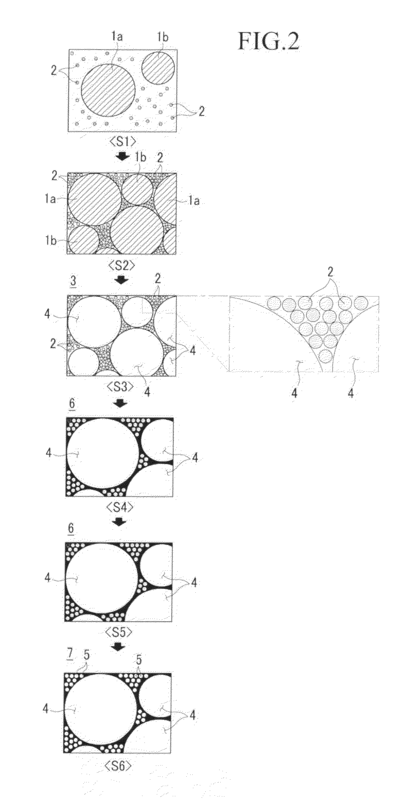
Preparation of Porous Carbon Structure
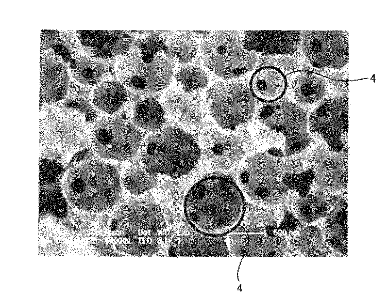
[0085]SiO2 having an average particle diameter of 20 nm was dispersed in a mixed solvent of alcohol, distilled water, and ammonia to provide a 1.2% concentration colloidal dispersion. 700 ml of the dispersion, 200 ml of polystyrene spheres having an average particle diameter of 250 nm, and 200 ml of polystyrene spheres having an average particle diameter of 500 nm were mixed to provide a mixture. The mixture was dried at 70° C. for 7 days. The dried resultant was fired at 550° C. for 7 hours to volatilize the polystyrene spheres to provide a template. The polystyrene spheres were removed to provide two kinds of macropores respectively having average pore diameters of 240 nm and 490 nm. Then, 4 ml of divinyl benzene was mixed with 0.1845 g of azobisisobutyronitrile to provide a carbon precursor solution. 2 g of the template was placed into the carbon precursor solution and was vapor-adsorbed to fill the pores between SiO2 particles with the carbo...
example 2
Preparation of Porous Carbon Structure
[0086]SiO2 having an average particle diameter of 20 nm was dispersed into a mixed solution of alcohol, distilled water, and ammonia to provide a 1.2% concentration colloidal dispersion. 700 ml of the dispersion was mixed with 133 ml of polystyrene spheres having an average particle diameter of 250 nm, 133 ml of polystyrene spheres having an average particle diameter of 500 nm, and 133 ml of polystyrene spheres having an average particle diameter of 1000 nm to provide a mixture. A porous carbon structure was obtained in accordance with the same procedure as in Example 1, except that the provided mixture was used.
example 3
Preparation of Porous Carbon Structure
[0087]A porous carbon structure was obtained in accordance with the same procedure as in Example 1, except that the polystyrene spheres having an average particle diameter of 250 nm and the polystyrene spheres having an average particle diameter of 500 nm were replaced with polymethyl(meth)acrylate spheres having an average particle diameter of 250 nm and polymethyl(meth)acrylate spheres having an average particle diameter of 500 nm.
PUM
| Property | Measurement | Unit |
|---|---|---|
| pore diameter | aaaaa | aaaaa |
| pore diameter | aaaaa | aaaaa |
| pore diameter | aaaaa | aaaaa |
Abstract
Description
Claims
Application Information