Composite air cooled turbine rotor blade

Inactive Publication Date: 2013-02-05
FLORIDA TURBINE TECH
View PDF2 Cites 67 Cited by
  • Summary
  • Abstract
  • Description
  • Claims
  • Application Information

AI Technical Summary

Benefits of technology

[0009]It is an object of the present invention to provide for a turbine rotor blade with a low cooling air flow

Problems solved by technology

However, the highest temperature gas than can be passed into the turbine is limited to the material properties of the turbine, especially the first stage stator vanes and rotor blades since these airfoils are exposed to the highest temperature gas flow.
However, the pressurized cooling air used for cooling of the airfoils is typically bled off from the compressor.
The cooling air thus is not used for producing mechanical work but reduces the efficiency of the engine. it is therefore us

Method used


Image

  • Composite air cooled turbine rotor blade
  • Composite air cooled turbine rotor blade
  • Composite air cooled turbine rotor blade

Examples


Example

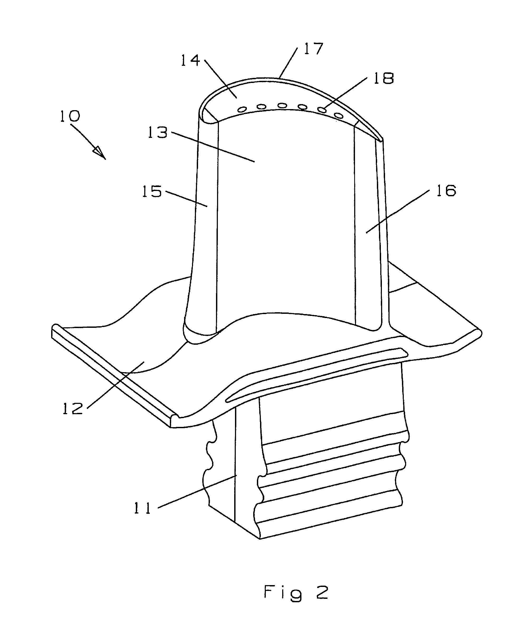
[0023]The present invention is a turbine rotor blade for use in a gas turbine engine such as an industrial gas turbine engine for the first stage blades. However, the blade cooling circuit can be used for an aero engine blade as well. FIG. 2 shows the turbine rotor blade 10 of the present invention with a root 11, a platform 12 that forms a flow path for the hot gas flow passing through the turbine, and an airfoil extending from the platform that includes a leading edge 15 and a trailing edge 16 with a pressure side wall 13 and a suction side wall extending between the two edges. A blade tip 14 includes a single suction side tip rail 17 that extends from the trailing edge and around the leading edge and stops around the leading edge on the pressure side wall. A row of pressure side tip cooling slots 18 open onto the tip floor that connect the blade internal cooling air circuit. The tip cooling holes 18 extend along the pressure side edge of the tip from the leading edge ceramic piec...


PUM


Abstract

A composite turbine rotor blade that uses the high heat resistance capability of a ceramic material along with the high strength capability of a high strength metallic material. A main body or insert piece with a leading edge, a trailing edge and a blade tip is made from a single piece of CMC, Carbon/Carbon or high temperature resistant metallic material such as Columbium or Molybdenum. A pressure side wall piece and a suction side wall piece both made of the metallic material that is bonded together to sandwich in-between the insert piece. The insert piece includes a number of cross-over holes in which locking pins pass through from one of the two metallic pieces and form bond surfaces to bond the two metallic pieces together with the insert piece sandwiched in-between. The two metallic pieces each include a serpentine flow cooling circuit to provide cooling air flow form the metallic pieces.

Description

GOVERNMENT LICENSE RIGHTS[0001]None.CROSS-REFERENCE TO RELATED APPLICATIONS[0002]None.BACKGROUND OF THE INVENTION[0003]1. Field of the Invention[0004]The present invention relates generally to a gas turbine engine, and more specifically to an air cooled turbine rotor blade with near wall cooling.[0005]2. Description of the Related Art including information disclosed under 37 CFR 1.97 and 1.98[0006]A gas turbine engine, such as an industrial gas turbine (IGT) engine, includes a turbine with multiple rows or stages or stator vanes that guide a high temperature gas flow through adjacent rotors of rotor blades to produce mechanical power and drive a bypass fan, in the case of an aero engine, or an electric generator, in the case of an IGT. In both cases, the turbine is also used to drive the compressor.[0007]The efficiency of the engine can be increased by passing a higher temperature gas flow into the turbine section. However, the highest temperature gas than can be passed into the tur...

Claims


Application Information

Patent Timeline
IPC IPC(8): B63H1/14B64C11/00B63H7/02F03D11/02F01D5/18F04D29/58F01D5/08
CPCF01D5/147F01D5/187F01D5/20F01D5/282F05D2240/303F05D2240/304F05D2240/307F05D2250/185F05D2260/36F05D2300/6033
Inventor LIANG, GEORGE
Owner FLORIDA TURBINE TECH
Why Eureka
Try Eureka