Medical apparatus with image acquisition device and position determination device combined in the medical apparatus

Inactive Publication Date: 2013-02-12
SIEMENS HEALTHCARE GMBH
View PDF10 Cites 37 Cited by
  • Summary
  • Abstract
  • Description
  • Claims
  • Application Information

AI Technical Summary

Benefits of technology

[0014]An object of the present invention is to provide a medical apparatus having an image acquisition device and a position determination device, combined therein that links, in a simple manner, the imaging components and position determination components (the navigation hardware).
[0015]The above object is achieved in accordance with the invention by a medical apparatus for acquisition of images of at least one region of the body of a patient by means of an image acquisition device, with at least one position determination device that serves for determination of the position of at least one medical instrument within an operation region being arranged at the medical apparatus. By the arrangement of the position determination device at the medical apparatus and therewith the fixed connection of the position determination device with the medical apparatus, the need for additional configuration, reconfiguration or alignment of the position determination device is avoided. Due to the fixed connection, the position determination device of the navigation system and the image acquisition device are also no longer subjected to an uncontrolled relative movement relative to one another. The coordinate transformation that is implemented one time between the coordinate system of the position determination device and the coordinate system of the image acquisition system thus can be retained. A repeated calibration procedure after a spatial variation of the medical apparatus can be entirely omitted. The position determination device is mounted on the medical apparatus such that its sensors have an unobstructed detection area (field of view) at the operation region. This is normally already achieved by a free, non-limited view (thus a view that is not occluded or blocked by other objects that are not transparent for the sensor) being enabled at the site of the intervention.
[0016]The sensors of the position determination device can be based on optical, magnetic, ultrasound-based, radio-based or infrared-based sensing techniques Mixed forms of these techniques can also be advantageously used, such mixed forms in combination increasing the precision of the position determination of the medical instruments and improving the failure susceptibility due to possibly redundant systems. It is thus possible to use some optical sensors (which are normally CCD cameras) and to supplement these with sensors that, for example, are based on a magnetic position determination method. It would also be conceivable to supplement optical systems with systems that operate on the basis of measurements of the reflections produced by the medical instruments. With the integration of the position determination device into the medical apparatus, these will inevitably be positioned closer to the actual operation region than is the case given the conventional separate systems, and new possibilities for use of position-determining sensors therewith result. Other position determination methods (for example infrared) can also result from this arrangement that are not yet used today due to the greater separation (distance) between operation region and the position determination device. Due to the smaller separation from the operation field, the position determination device can naturally also be designed much smaller, lower-power and thus also normally more cost-effectively. Additional navigation hardware in the operating room can be foregone due to the integration of the position determination device into the medical apparatus, The position determination device is positioned closer to the operation field so the visibility of the medical instruments to the navigation hardware is distinctly improved. The operating team can move more freely without significantly limiting the visibility of the medical instruments with their bodies.

Problems solved by technology

Other position determination methods (for example infrared) can also result from this arrangement that are not yet used today due to the greater separation (distance) between operation region and the position determination device.

Method used


Image

  • Medical apparatus with image acquisition device and position determination device combined in the medical apparatus
  • Medical apparatus with image acquisition device and position determination device combined in the medical apparatus

Examples


Embodiment Construction

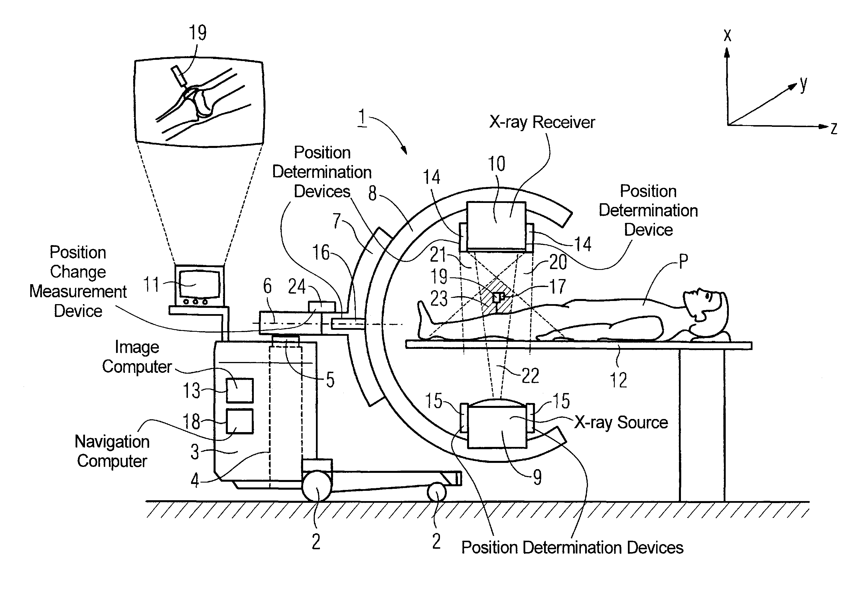
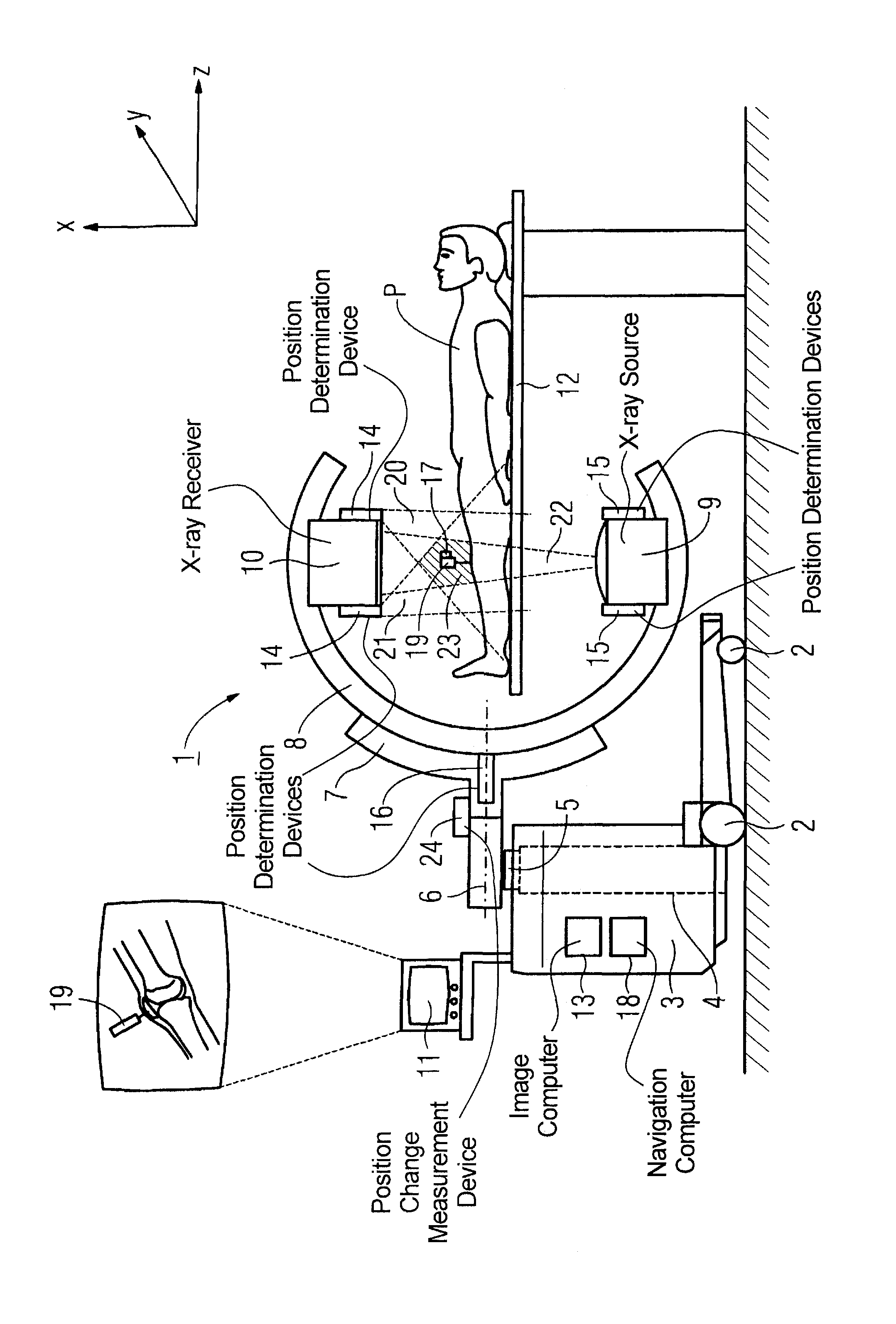
[0027]A C-arm x-ray apparatus 1 with an apparatus cart 3 that can be moved on wheels 2 is schematically shown in FIG. 1. A lifting device 4 (schematically indicated) with a column 5 that serves for displacement of the mounting part6 along the rotation axis z runs within the apparatus cart 3. A mounting device 7 that accommodates the C-arm 8 is mounted on the mounting part 6. The connection of the mounting device 7 with the mounting part 6 allows a rotation of the C-arm 8 connected with the mounting device 7. An x-ray source 9 and an x-ray receiver 10 are mounted opposite one another on the C-arm 8. The x-rays emitted from the x-ray source and striking the x-ray receiver 10 form the acquisition region 22 of the x-ray radiation.

[0028]In the exemplary embodiment, the x-ray receiver 10 is a known solid-state detector. The x-ray images acquired with the x-ray detector can be shown in a known manner on a display device 11. The C-arm x-ray apparatus 1 shown in FIG. 1 allows the production ...


PUM


Abstract

In a medical apparatus for implementation of operative procedures on a patient, an image acquisition device and a position determination device combined and permanently associated in the medical apparatus. The position determination device serves for determination of the position of at least one medical instrument within an operation region.

Description

BACKGROUND OF THE INVENTION[0001]1. Field of the Invention[0002]The present invention concerns a medical apparatus for implementation of operative procedures on a patient with image acquisition device and position determination device combined in the medical apparatus.[0003]2. Description of the Prior Art[0004]During operative procedures on a patient, the control of surgical instruments (such as, for example, laparoscopes, endoscopes, needles, etc.) often ensues by means of various image-supported methods.[0005]In the simplest case, purely image-supported positionings of medical instruments are implemented, meaning that the instrument position is directly visible and can be tracked in the image. Examples of this are the needle guidance (for example for biopsies or RF ablations) by means of ultrasound, CT fluoroscopy or x-ray fluoroscopy. These methods are characterized by real-time capability and are standards today in specific application fields.[0006]Another widespread method is t...

Claims


Application Information

Patent Timeline
Patent Type & Authority Patents(United States)
IPC IPC(8): A61B5/055G01D18/00A61B6/08
CPCA61B6/12A61B19/52A61B19/5244A61B2019/5238A61B34/20A61B90/36A61B2090/376G16H30/20G16H40/63
Inventor GRAUMANN, RAINER
Owner SIEMENS HEALTHCARE GMBH
Why Eureka
Try Eureka