Porous materials embedded with nanoparticles, methods of fabrication and uses thereof

a technology of porous materials and nanoparticles, applied in the field of porous materials embedded with nanoparticles, can solve the problems of inability to manufacture in an economical manner, inability to meet the requirements of operation, and large volume of absorbers, and achieve the effect of less labor-intensive production and easy implementation

Inactive Publication Date: 2013-02-19
TISHIN ALEKSANDR METTALINOVICH +1
View PDF18 Cites 45 Cited by
  • Summary
  • Abstract
  • Description
  • Claims
  • Application Information

AI Technical Summary

Benefits of technology

[0093]The wave absorber was obtained by molding of polyethylene (PE) using Carbon dioxide (CO2) as physical foaming agent, which is a low cost and non-flammable gas with good blowing power and fast dissolution in polymers. In the premixed 25 g of precursor mixture of the polyethylene polymer 20 g of nickel particles having 10 nm to 25 nm size were admixed for 10 min mixing time. The opposite walls of the mould were made of magnet material to form a magnetic field of 2 T. After cooling, the articles were extracted from the forms, cut into pieces of equal length and weighted to measure the density of the articles. The density was 2.5 g / cm2 in the vicinity of the magnetic walls as compared to the density of the articles, 2.0 g / m2 obtained in a regular moulds that were not subjected to magnetic filed. Further, the electrical conductivity of the articles produced in the magnetic forms was 100 OM.mm (50 Hz) compared to 1.5 Om.mm in the absence of magnetic field. A particularly important advantage of the present invention is that the inventive process for making the three-dimensional body enables its fabrication (a) as a unified whole, (b) from a single mixture of initial substances, including a precursor material and particles, meaning that, unlike the prior art, it need not be formed as a laminate comprising a plurality of layers laminated together with bonding layers, wherein each layer has to be manufactured from a separate precursor mixture with different composition, so that the process of laminating them together results in a stepwise change in particle concentration. According to the inventive process, a concentration gradient is provided by exposure of a semi-solidified viscous precursor mixture to a magnetic or electromagnetic field of predetermined geometry to form the desired gradient of particles distribution and thus, the desired gradient of electromagnetic and other properties.
[0094]In other words, the present invention resolves prior art problems concerning a predictable process for fabricating a bulk absorber having a continuous concentration gradient of property-altering particles along one or more dimensions of the bulk absorber body, so that it is no longer necessary to create a plurality of layers, or mix separate flows of polymers precursors, each having a different concentration of particles, and then combining them together to create a stepwise or continuous particle concentration gradient. The inventive process and product is much easier to implement and much less labor-intensive to make than the prior art approach.C. Manufacturing System for Fabricating Porous Magnetic Material
[0095]In another aspect of the invention a manufacturing system for fabricating the bulk absorber comprises mixing devices, control means, a source of electromagnetic radiation, positioning means, and forming means.
[0096]The mixing means produce a precursor mixture of a polymer precursor and magnetic nanoparticles, which are fed by delivery devices such as vibrational feeders. The control means varies the ratio of the flow of particles and precursor polymer. The control means may be any suitable device or control system for controlling the flow rates of precursors.
[0097]The positioning means deposits the pre-mix in a predetermined form to build a non-solidified item, and adjust the relative position of the mould with non-solidified item a source of magnetic radiation. The positioning means may comprise a translation means and / or a rotation means for changing the location of the mould in a horizontal direction relative to the source of magnetic radiation.
[0098]The forming means is for solidifying the non-solidified item into the bulk absorber. In an aspect of the invention, when the polymer is thermosetting material, the solidifying means sinters the non-solidified item in a sintering oven. Alternatively, when the polymer is cross-linking material, the forming means can be a source of cross-linking agent, or a source of cross-linking radiation. When the polymer is a foaming, the forming means comprise a foaming chemical or physical agent, and so on.

Problems solved by technology

While such broadband absorbers and antennas have hitherto been produced, they are typically quite bulky, heavy, and generally ill-suited for operational use in those situations where low bulk and light weight are of paramount importance.
Furthermore, even with absorbers satisfying both low bulk and low weight requirements, it often turns out that the absorber construction is so complex as to render impractical its production in an economical manner.
The reduced radar reflectivity reduces the range of detectability of the antenna by possible adversaries.
There are numerous disadvantages to the prior art bulk absorbers, lens and concentrators with a discontinuous dielectric or magnetic altering property gradient.
The discontinuities in these materials, due to the step-wise changes in the dielectric or magnetic altering property gradient, cause deflection or reflection of the waves that are meant to be focused or, opposite, absorbed.
Additionally, the bond layer in between the adjacent billets also causes possible deflection or reflection of the waves.

Method used


Image

  • Porous materials embedded with nanoparticles, methods of fabrication and uses thereof
  • Porous materials embedded with nanoparticles, methods of fabrication and uses thereof
  • Porous materials embedded with nanoparticles, methods of fabrication and uses thereof

Examples


examples of preparation

Example 1

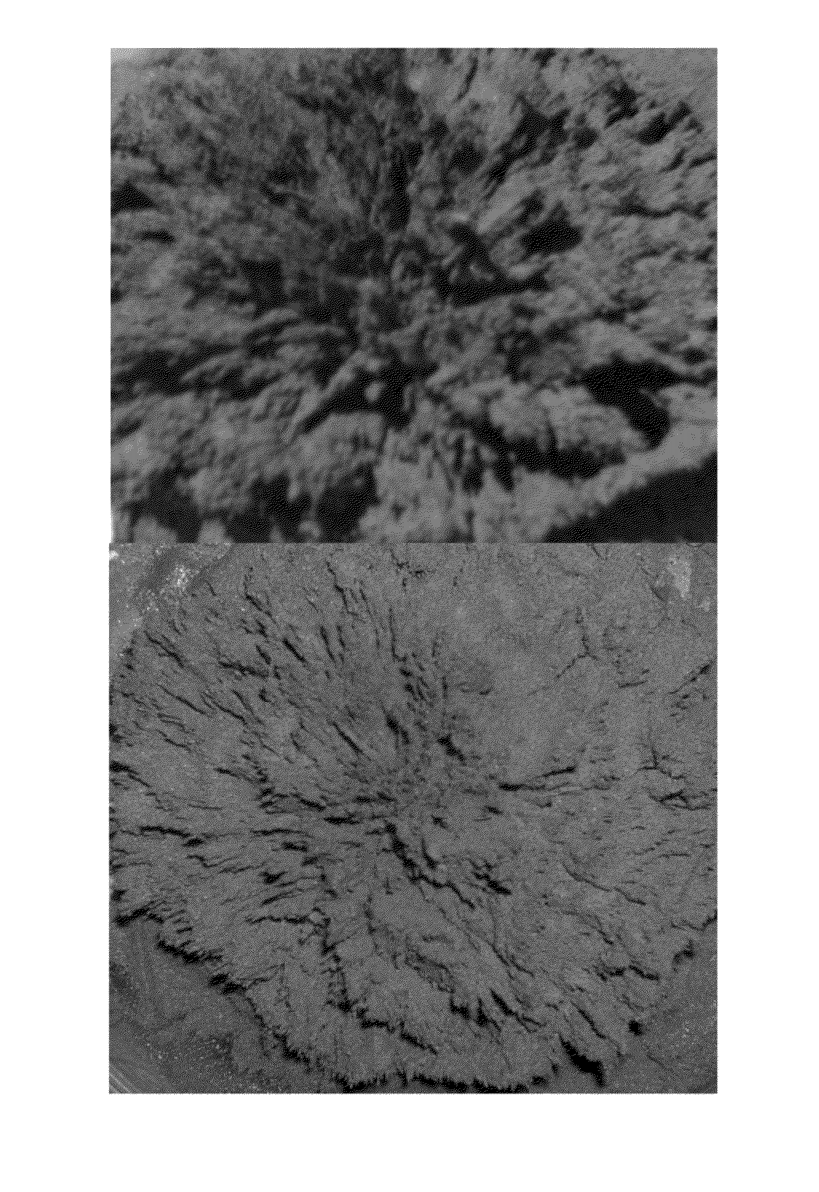
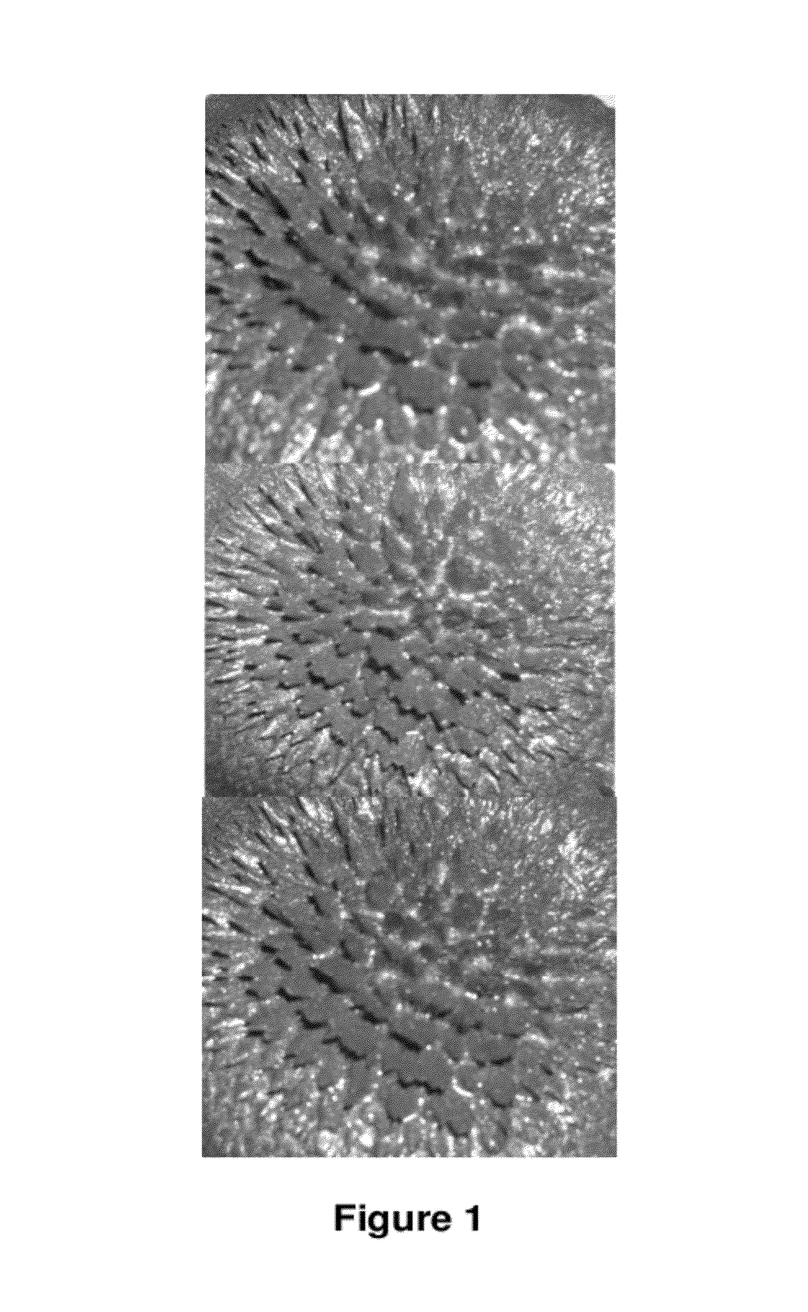
[0118]As a polymer precursor, 9 g of epoxy resin ED-20 (epoxy-diane resins formed by reaction of bisphenols A or F with epichlorohydrine) available from Chimex Ltd, St. Petersburg, Russia) and 1-2% mas of curing agent triethylenetetramine (TETA) (foaming at ambient temperature 20° C.) were mixed in a form with 2-5 mass parts of microspheres having bulk density of 200 kg / m3. After 7-8 minutes of through mixing, 1 to 3 g of commercially available nanoparticles of Fe R-10, (30 nm to 150 nm, initial μ2,000-3,000, specific permeability 0.1 MκOM / M) obtained by reaction Fe(CO)5=Fe+5CO, available from OAO Sintez, Nizhni Novgorod, were added and the mixing was continued for another 7 min. Then, the mixture was subjected to magnetic field having intensity around 300 mT at a distance of 0.5 mm from the surface, generated by a permanent magnet NbFeB (Hcj 880-1595 Ka / m), available from PolyMagnet Ltd, Moscow, and left for 20-180 min. See a magnetic field map used to prepare the articles...

example 2

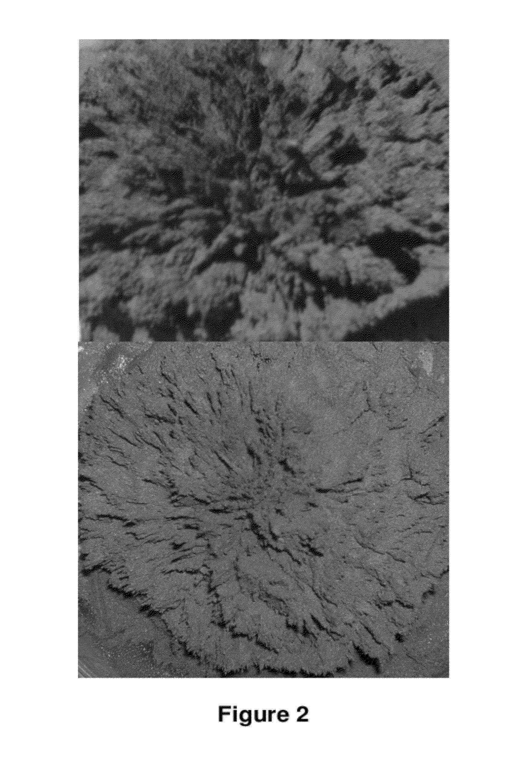
[0123]As a polymer precursor, 10 g of epoxy resin ED-20 (epoxy-diane resins formed by reaction of bisphenols A or F with epichlorohydrine) available from Chimex Ltd, St. Petersburg, Russia) and 1.5-2.5% mas of curing agent triethylenetetramine (TETA) (foaming at ambient temperature 20 C) were mixed in a form with a foaming system consisting of 1.0-2.0 mass parts of liquid glass and 0.25-1.50 mass parts of A1 particles (10-50 mcm). After 3-5 minutes of through mixing, 10 to 30 g of commercially available nanoparticles of Fe R-10, (30 nm to 150 nm, initial μ 2,000-3,000) obtained by reaction Fe(CO)5=Fe+5CO, available from OAO Sintez, Nizhni Novgorod, were added and the mixing was continued for another 7 min.

[0124]Then, the mixture was subjected to magnetic field having intensity around 300 mT at a distance of 0.5 mm from the surface, generated by a permanent magnet NbFeB (Hcj 880-1595 Ka / m), available from PolyMagnet Ltd, Moscow, and left for 20-180 min. See a magnetic field map used ...

example 3

Preparation of a Polymer Composition Based on Polyurethane Granules, Nanoparticulate Filler and Solid Salicylic Acid as Blowing Agent

[0128]The composition is a foaming system of a well-known type comprising thermoset polymers of the type used with surfactants, blowing agents and a catalyst system. A typical core formulation may be as follows:

[0129]Nylon 12 Microporous foam embedded with manganese ferrite MnFe2O4 nanoparticles having size 1 nm to 30 nm.

[0130]Solid Nylon 12 pellets were heated with solid salicylic acid to form a 30% (by weight) isotropic solution while using mechanical stirring. About 10% of manganese ferrite nanoparticles were added under continuous stirring. A magnetic field of 2 T was applied in the direction transversely the axis of the mechanical mixer for a period of 30 minutes. After thorough mixing the solution was heated to about 190° C. in an inert atmosphere and the vessel was then quenched in liquid nitrogen. The solid foam obtained was washed with chlorof...


PUM

PropertyMeasurementUnit
frequenciesaaaaaaaaaa
diameteraaaaaaaaaa
particle sizeaaaaaaaaaa

Abstract

The present invention relates to porous structures embedded with nanoparticles, methods of forming the structures, and methods of using the structures. In most general form, the invention relates to porous materials embedded with nanoparticles having characteristics, such as magnetic, enabling to align or arrange the nanoparticles in the material by exposure, e.g. to a magnetic field. Therefore, a method according to the invention provides manufacturing materials having variable magnetic and electromagnetic properties which can be adapted during manufacture for various applications, such as electromagnetic wave absorbers, lens, concentrators, etc.

Description

CROSS-REFERENCES TO RELATED APPLICATIONS[0001]This application claims the benefits from International Application PCT / RU2008 / 000813 filed on Dec. 29, 2008 and priority application RU 2007149614 filed on Dec. 28, 2007. The contents of these applications are hereby incorporated by reference and in their entirety.FIELD OF THE INVENTION[0002]The present invention relates to porous structures embedded with nanoparticles, methods of forming the structures and uses thereof. In most general form, the invention relates to porous polymer materials embedded with nanoparticles having characteristics, such as magnetic, enabling to align or arrange the nanoparticles in the material by exposure, e.g. to lines of magnetic force. Therefore, a method according to the invention provides manufacturing materials having variable magnetic and electromagnetic properties which can be adapted for various applications, such as electromagnetic wave absorbers, wave lens, concentrators and similar devices.BACKGR...

Claims


Application Information

Patent Timeline
Patent Type & Authority Patents(United States)
IPC IPC(8): H01Q17/00H01Q15/00
CPCC04B38/02C04B38/10C08J9/0066C08J9/40H05K9/0075C04B14/34C04B26/02C04B38/0058C04B40/0209C04B35/80C04B26/16C04B2111/00258C04B2111/0037C04B2111/00422C04B2111/90G02B1/002
Inventor TISHIN, ALEKSANDR METTALINOVICHHALILOV, SAMED VEISALKARA OGLY
Owner TISHIN ALEKSANDR METTALINOVICH
Why Eureka
Try Eureka