
Platform-independent method and system for deploying control logic programming

a platform-dependent, control logic technology, applied in the direction of program control, process and machine control, etc., can solve the problems of affecting the ability of manufacturers to quickly and seamlessly adopt new technology, and general lack of interchangeability or platform flexibility. to achieve the effect of improving the flexibility of an overall or global control system

Active Publication Date: 2013-02-19
GM GLOBAL TECH OPERATIONS LLC
View PDF9 Cites 6 Cited by
  • Summary
  • Abstract
  • Description
  • Claims
  • Application Information

AI Technical Summary

Benefits of technology

This patent provides a way to create control applications that can work on different types of hardware platforms made by different companies. The system converts high-level control logic into specific code that can be easily used on different platforms. This improves flexibility and makes it easier to develop and test control applications. The code is generated using a common method, and then is validated and deployed to the plant floor with minimal effort.

Problems solved by technology

That is, implementation code that is uniquely written for execution on hardware provided by Vendor A is ordinarily not readily executable on hardware provided by Vendor B. This general lack of interchangeability or platform flexibility can be detrimental to manufacturers having a diverse base of operations, and in particular to global manufacturers having a hefty prior investment in widely disparate control-related hardware and software throughout its various manufacturing plants and other facilities.
As a result, the costs associated with the acquisition and / or ongoing operations and maintenance of a control system can quickly escalate whenever a critical component or software update must be sole-sourced.
Likewise, a given manufacturer's ability to quickly and seamlessly adopt new technology can be affected by vendor-specific or sole-source requirements.
While some options exist for minimizing the effects of this general lack of flexibility, such as requiring all vendors to follow a single standard, standardizing all equipment and / or software on a single vendor or provider, and / or developing a software-based coupled translator between different vendor platforms, such solutions can be prohibitively expensive or impracticable for existing manufacturers to implement.

Method used


Image

  • Platform-independent method and system for deploying control logic programming
  • Platform-independent method and system for deploying control logic programming
  • Platform-independent method and system for deploying control logic programming

Examples


Embodiment Construction

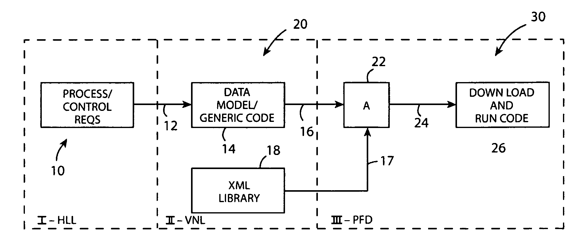
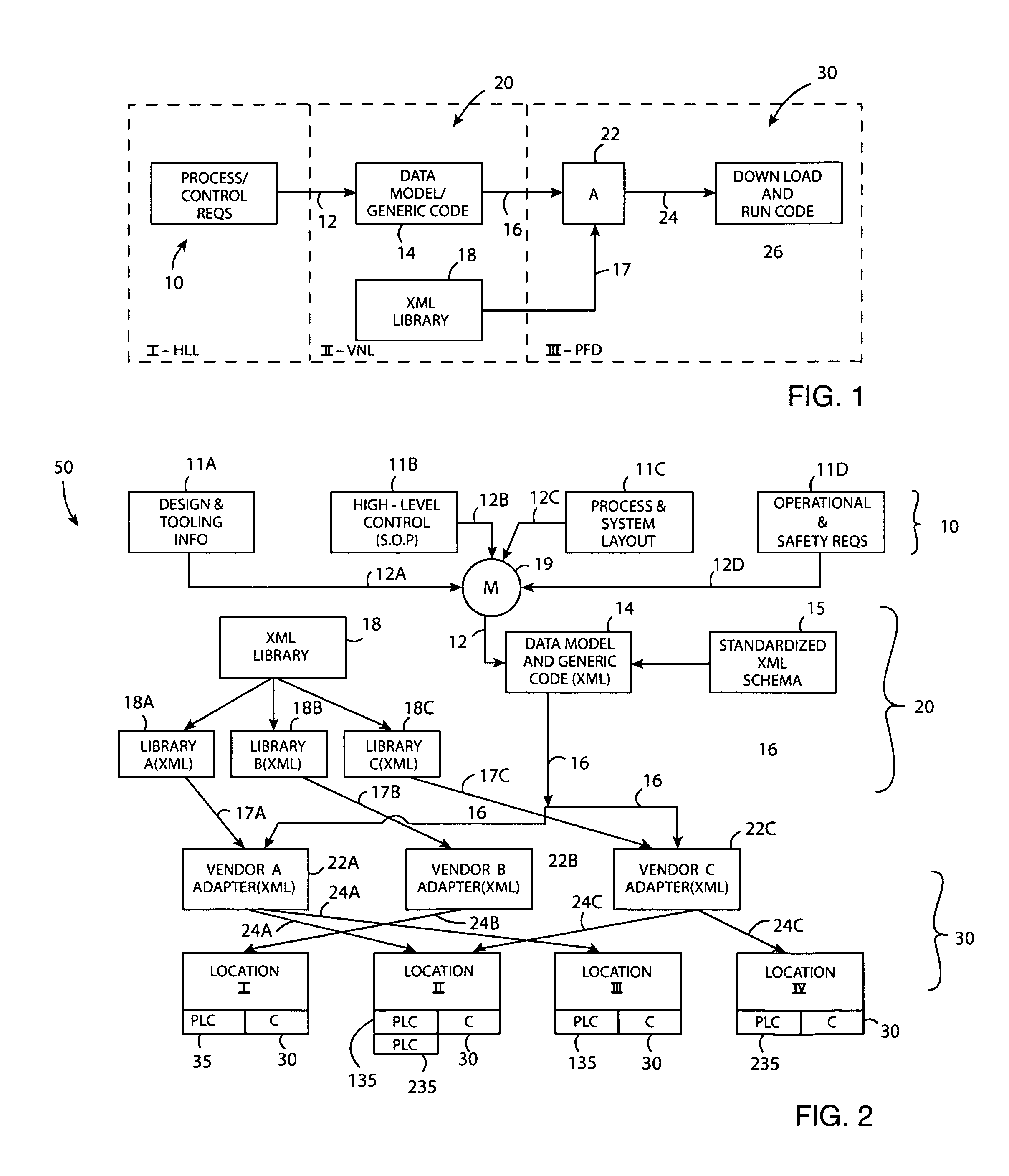
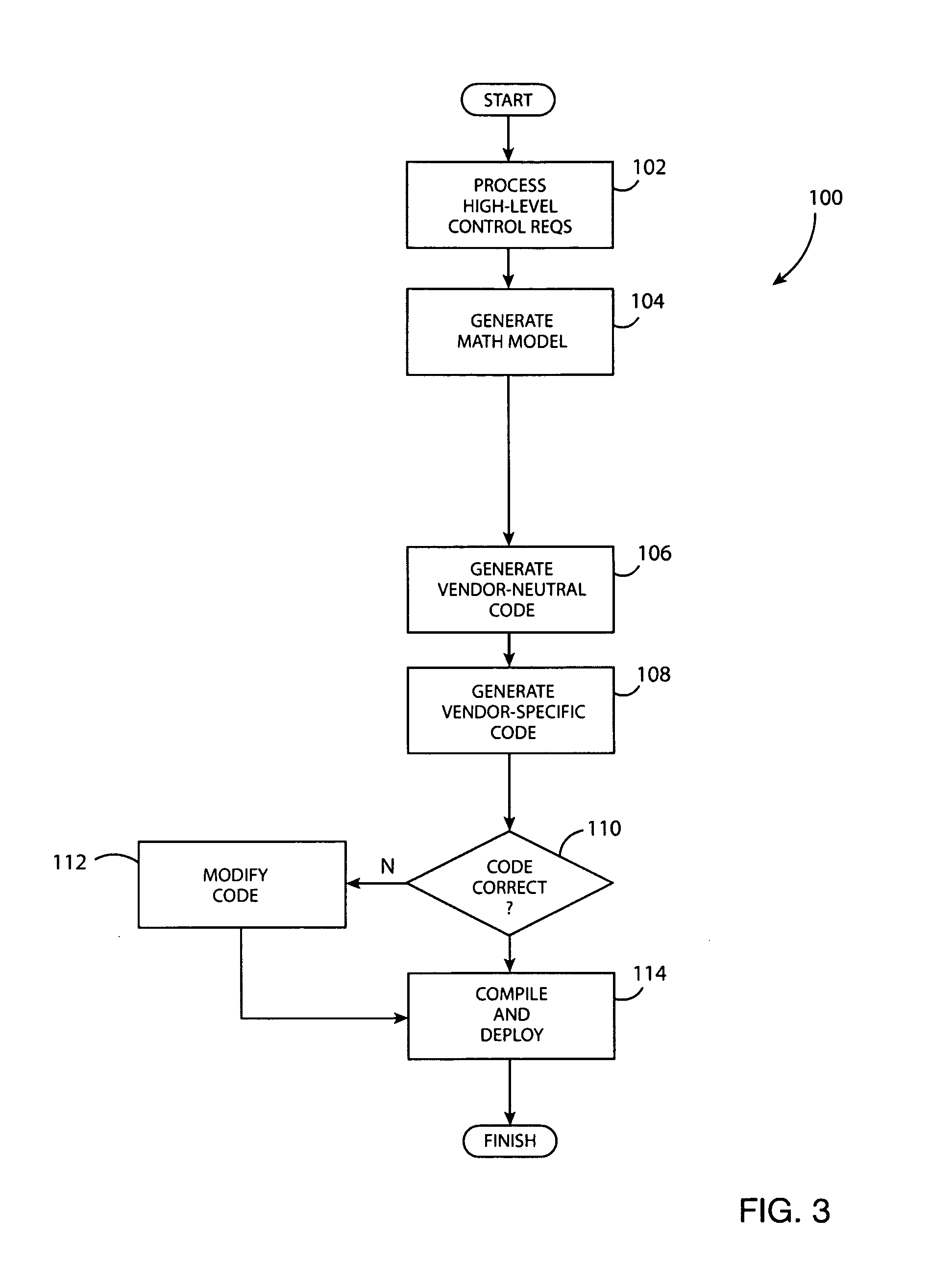
[0014]Referring to the drawings, wherein like reference numbers correspond to like or similar components throughout the several figures, and beginning with FIG. 1, a framework for seamlessly employing automatic control applications to various different vendor platforms includes three processing layers: a first processing layer or High-Level Logic Layer (HLL) 10, a second processing layer or Vendor-Neutral Logic Layer (VNL) 20, and a third processing layer or vendor and / or platform-specific Plant Deployment Layer (PDL) 30. That is, the multi-layer framework exemplified in the logic flow diagram of FIG. 1 can be implemented using the system 50 of FIG. 2 described below in order to convert high-level or overarching control requirements and information from a generic form, using automatically-generated mathematical models, into plant-floor or production ready implementation code that can be executed using the hardware of any number of existing programmable logic controllers (PLC), regar...


PUM


Abstract

A system for generating platform-specific control logic implementation code for execution on a programmable logic controller (PLC) platform includes a plurality of processing layers. A first layer models generic control requirements as a unitary mathematical model (UMM). A second layer translates the UMM into generic control code describing a platform-independent set of generic control functions following an open structured language. A third layer automatically transforms the generic control functions into the platform-specific implementation code executable on different PLC platforms. A method of generating the implementation code includes modeling control requirements as a mathematical model, transforming the model into platform-independent control code describing a predetermined set of generic control functions using Extensible Markup Language (XML) schema, and automatically transforming the generic control functions into the implementation code.

Description

TECHNICAL FIELD[0001]The invention relates generally to a framework for deploying control logic programming, and in particular to an automated method and system for converting generic high-level control requirements into production-ready and platform-specific implementation code.BACKGROUND OF THE INVENTION[0002]A programmable logic controller or PLC is a special purpose digital computing machine or device used for controlling the operation of an electromechanical system and / or associated process. A detailed software program or set of implementation code specifies the precise manner in which a particular machine or process is to operate, and is compiled and downloaded from a host machine or computer to a memory location aboard the PLC prior to execution. Once the implementation code is downloaded to the PLC, the PLC is switched over to run mode, and the ensuing control sequence is executed automatically until such time as the implementation code is interrupted or stopped.[0003]While ...

Claims


Application Information

Patent Timeline
Patent Type & Authority Patents(United States)
IPC IPC(8): G06F9/44
CPCG05B19/056G06F8/35G06F8/41
Inventor YUAN, CHENGYINBILLER, STEPHAN R.YEN, CHIEH-YI JERRYGU, FANGMING
Owner GM GLOBAL TECH OPERATIONS LLC
Learn More