Electrolytic igniter for rocket engines using monopropellants

a rocket engine and electrolytic technology, applied in the direction of rocket engine plants, machines/engines, hot gas positive displacement engine plants, etc., can solve the problems of high toxicity, additional complication, and provide a specific impulse that is limited in practice to 330 seconds, and achieves instantaneous power high level

Inactive Publication Date: 2013-03-05
ARIANEGRP SAS
View PDF12 Cites 2 Cited by
  • Summary
  • Abstract
  • Description
  • Claims
  • Application Information

AI Technical Summary

Benefits of technology

[0036]The invention also seeks to provide an ignitor of simplified construction applicable to a liquid mono-propellant rocket engine, which ignitor, in particular, does not pose particular problems of safety, and allows a combustion chamber to be ignited reliably, regardless of its size, with a very high level of instantaneous power being delivered.
[0037]In accordance with the invention, these objects are achieved by a mono-propellant rocket engine comprising a main combustion chamber, an electrolytic ignitor, and a main injector, the electrolytic ignitor comprising an injector constituting a first electrode and including a device for injecting a first liquid mono-propellant that is electrically conductive, a second electrode that is electrically insulated from the injector by an insulator, a tank for said first mono-propellant, a solenoid valve interposed between said tank and a distribution channel serving to dispense the first mono-propellant in said first mono-propellant injector device constituted by at least one injection hole opening out in the vicinity of the second electrode, and an electrical power supply circuit, the main injector being situated in the vicinity of the second electrode to inject jets of a second liquid mono-propellant into the main combustion chamber of the rocket engine, the rocket engine being characterized in that the second electrode extends downstream beyond the injector, in that the first liquid mono-propellant is injected via said injection hole in the form of a free jet that strikes the second electrode in a zone situated outside the body of the injector, and in that the electrical power supply circuit is adapted to raise the second electrode to a potential lying in the range 50 V to 1000 V relative to the potential of the first electrode, in such a manner that the dissipation of electrical power by ionic conduction in the free jet of the first mono-propellant injected via said injection hole is capable of causing temperature to rise sufficiently to lead to spontaneous decomposition of the first mono-propellant and to the production of combustion gas for ensuring ignition of the jets of the second mono-propellant coming from the main injector.

Problems solved by technology

Self-ignition makes use of self-igniting propellants such as mono-methyl hydrazine (MMH) and nitrogen peroxide (N2O4), which are well known, but which present high levels of toxicity and provide a specific impulse that is limited in practice to 330 seconds.
Nevertheless, self-ignition leads to an additional complication.
Certain liquids that self-ignite with oxygen, such as organometallic compounds, are spontaneously combustible in air, toxic, and cause burns by contact.
They therefore present safety problems.
In both circumstances, the high voltage used (10 kilovolts (kV) to 20 kV) can give rise to difficulties.
Hydrazine is a mono-propellant that decomposes catalytically and that also presents a high level of toxicity.
Nevertheless, that solution is restricted to a single use, or to a small number of ignitions if multiple pyrotechnic charges are used.
Such a restriction is thus incompatible with applications that require a large number of successive ignitions.
Nevertheless, spark plug ignition does not deliver sufficient energy to ensure the initial rise in pressure.
That gives rise to additional complication.
Self-ignition gives rise to similar complication in a two-propellant propulsion system (e.g. of the MMH-N2O4 type).

Method used


Image

  • Electrolytic igniter for rocket engines using monopropellants
  • Electrolytic igniter for rocket engines using monopropellants
  • Electrolytic igniter for rocket engines using monopropellants

Examples


Embodiment Construction

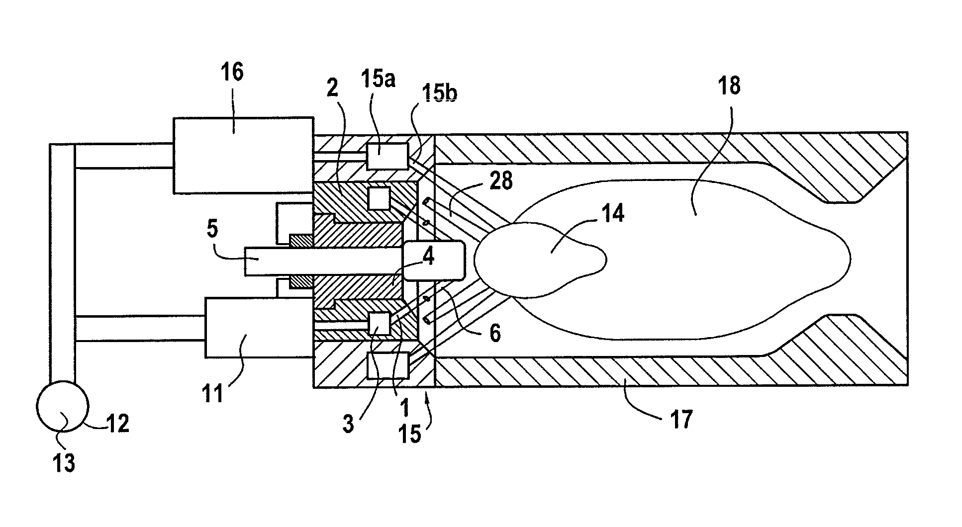
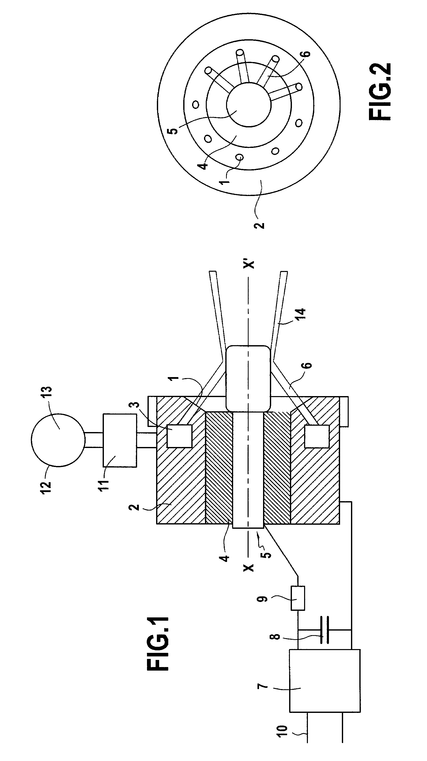
[0071]With reference to FIG. 1, there can be seen a first example of an electrolytic ignitor of the invention designed to be incorporated in a main injector that is for mounting to a combustion chamber of a mono-propellant rocket engine.

[0072]The electrolytic ignitor comprises an injector 2 that, in the example described, presents a potential close to electrical ground and constitutes a cathode.

[0073]The injector 2 comprises an electrolytic injector device with an electrolyte distribution channel 3 associated with at least one injection hole 1, or preferably with a plurality of injection holes 1 enabling free jets to be projected towards a central electrode 5 that is electrically insulated from the body of the injector 2 by an insulator 4.

[0074]In the example described, the central electrode 5 forms an anode and extends axially downstream beyond the injector 2.

[0075]The electrolyte distributor 3 is fed via a solenoid valve 11 from a tank 12 containing an electrolyte 13 that is advan...


PUM


Abstract

The electrolytic ignitor comprises an injector constituting a first electrode, a second electrode that is electrically insulated from the injector and that extends downstream beyond the injector, and a distribution channel to deliver a first mono-propellant to a first mono-propellant injector device constituted by at least one injection hole opening out in the vicinity of the second electrode, and an electrical power supply circuit adapted to raise the second electrode to a potential lying in the range 50 V to 1000 V relative to the potential of the first electrode. The electrical power dissipated by ionic conduction in the free jet of the first mono-propellant is suitable for giving rise to spontaneous decomposition of the first mono-propellant and for producing combustion gas that ensures ignition of jets of a second mono-propellant coming from a main injector situated in the vicinity of the second electrode.

Description

FIELD OF THE INVENTION[0001]The present invention relates to an electrolytic ignitor for a mono-propellant rocket engine, and to a mono-propellant rocket engine fitted with such an electrolytic ignitor.PRIOR ART[0002]Rocket engines fed with liquid propellants are generally ignited by self-ignition or by pyrotechnic ignition, or by electrical ignition using a torch.[0003]Self-ignition makes use of self-igniting propellants such as mono-methyl hydrazine (MMH) and nitrogen peroxide (N2O4), which are well known, but which present high levels of toxicity and provide a specific impulse that is limited in practice to 330 seconds.[0004]Some rocket engines operating on liquid oxygen and hydrocarbon are ignited by injecting a self-igniting liquid together with liquid oxygen, e.g. using an organometallic compound (as is done in the RD-180 engine from the Russian supplier NPO Energomash).[0005]Nevertheless, self-ignition leads to an additional complication. Certain liquids that self-ignite with...

Claims


Application Information

Patent Timeline
Patent Type & Authority Patents(United States)
IPC IPC(8): F02C7/264
CPCF02K9/52F02K9/95
Inventor VALENTIAN, DOMINIQUE
Owner ARIANEGRP SAS
Why Eureka
Try Eureka