Low distortion MOS attenuator

a low distortion, attenuator technology, applied in the direction of oscillator generators, pulse automatic control, pulse techniques, etc., can solve the problems of increasing cost, distortion of amplified signals, so as to increase the range of attenuation and minimize distortion

Active Publication Date: 2013-03-05
MURATA MFG CO LTD
View PDF12 Cites 3 Cited by
  • Summary
  • Abstract
  • Description
  • Claims
  • Application Information

AI Technical Summary

Benefits of technology

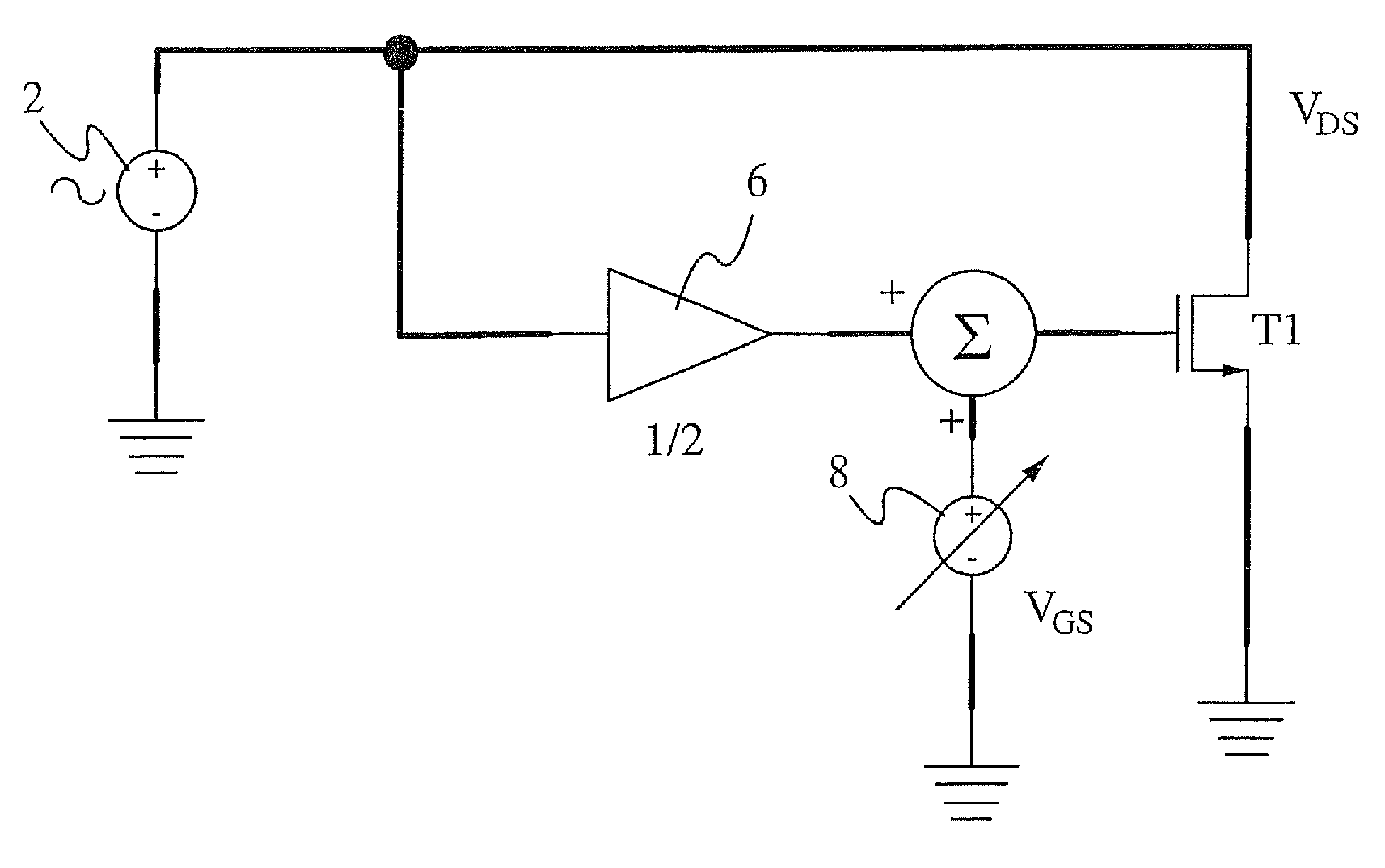
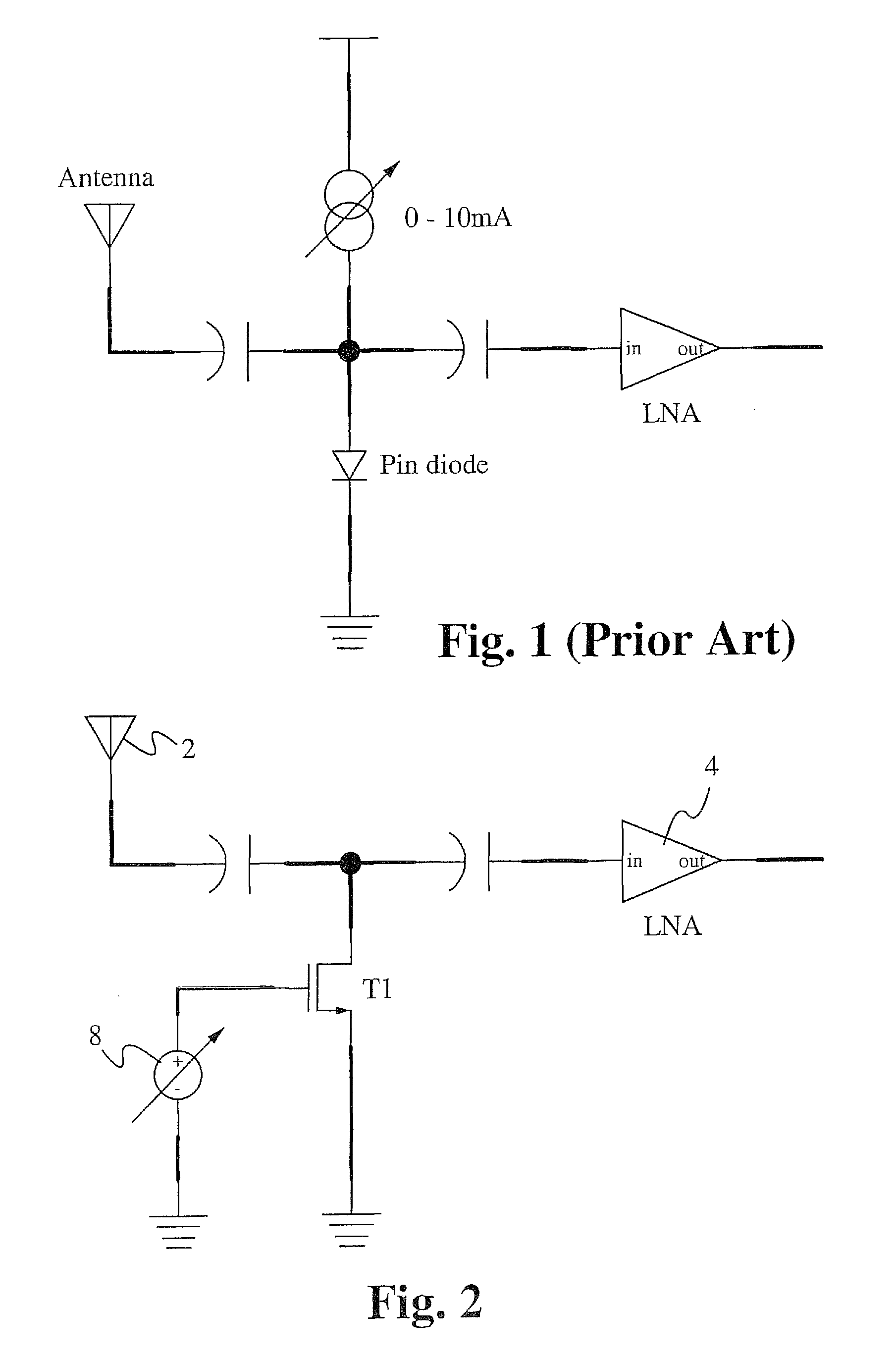
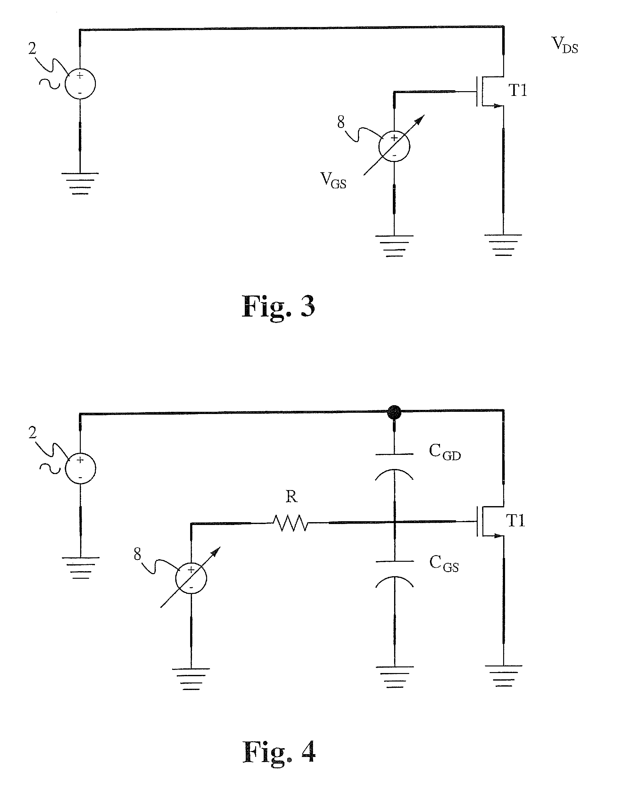
[0009]An attenuation circuit uses a transistor configured as a voltage controlled variable resistor as a signal attenuator for receivers operating in the zero Hz to about 30 MHz range. The transistor functions in the linear region to linearize the transistor resistance characteristics used for signal attenuation. In an exemplary application, the attenuation circuit is used as an RF attenuator for AM radio broadcast receivers and amplifiers with automatic gain control. Multiple attenuation circuits can be coupled in parallel, each attenuation circuit having a different sized variable resistance transistor, to form sequentially activated stages that increase the range of attenuation while minimizing distortion.

Problems solved by technology

Without such attenuation, input signals of sufficient signal strength overload the LNA, driving the LNA into a non-linear region and distorting the resulting amplified signal.
Without the variable resistance PIN diode, an RF signal of sufficient signal strength may overload the LNA, driving the LNA into a non-linear region that results in distortion of the amplified signal.
Although effective in providing signal attenuation, the variable resistance PIN diode is an external component that is not part of the radio receiver integrated circuitry resulting in increased cost.
Also, operation of the variable resistor PIN diode requires a significant amount of DC current.
As such, the variable resistance PIN diode suffers from cost and power consumption issues.
However, this approach introduces distortion within the LNA.

Method used


Image

  • Low distortion MOS attenuator
  • Low distortion MOS attenuator
  • Low distortion MOS attenuator

Examples


Embodiment Construction

[0021]Embodiments of the present application are directed to an attenuator. Those of ordinary skill in the art will realize that the following detailed description of the attenuator is illustrative only and is not intended to be in any way limiting. Other embodiments of the attenuator will readily suggest themselves to such skilled persons having the benefit of this disclosure.

[0022]Reference will now be made in detail to implementations of the attenuator as illustrated in the accompanying drawings. The same reference indicators will be used throughout the drawings and the following detailed description to refer to the same or like parts. In the interest of clarity, not all of the routine features of the implementations described herein are shown and described. It will, of course, be appreciated that in the development of any such actual implementation, numerous implementation-specific decisions must be made in order to achieve the developer's specific goals, such as compliance with...


PUM


Abstract

An attenuation circuit uses a voltage controlled variable resistance transistor as a signal attenuator for receivers operating in the zero Hz to about 30 MHz range. The transistor functions in the linear region to linearize the transistor resistance characteristics used for signal attenuation. In an exemplary application, the attenuation circuit is used as an RF attenuator for AM radio broadcast receivers and amplifiers with automatic gain control. Multiple attenuation circuits can be coupled in parallel, each attenuation circuit having a different sized variable resistance transistor, to form sequentially activated stages that increase the range of attenuation while minimizing distortion.

Description

RELATED APPLICATIONS[0001]This application claims priority of U.S. provisional application Ser. No. 61 / 290,481, filed Dec. 28, 2009, and entitled “Low Distortion CMOS Attenuator”, by these same inventors. This application incorporates U.S. provisional application Ser. No. 61 / 290,481 in its entirety by reference.FIELD OF THE INVENTION[0002]The present invention relates to the field of low distortion attenuators. More particularly, the present invention relates to the field of low distortion RF attenuators for a radio receiver.BACKGROUND OF THE INVENTION[0003]A low-noise amplifier (LNA) is an electronic amplifier used to amplify very weak signals, for example radio frequency (RF) signals captured by an antenna. In an exemplary application, an LNA is included in a front-end of an AM radio receiver. Using an LNA, the effect of noise from subsequent stages of the AM radio receiver is reduced by the gain of the LNA, while the noise of the LNA itself is injected directly into the received ...

Claims


Application Information

Patent Timeline
Patent Type & Authority Patents(United States)
IPC IPC(8): H03L5/00
CPCH03H11/245
Inventor MEYER, ROBERT GBIRKELAND, JOEL D
Owner MURATA MFG CO LTD
Why Eureka
Try Eureka