
Integrated process for steam cracking

a technology of steam cracking furnace and integrated process, which is applied in the direction of separation process, hydrocarbon oil treatment product, furnace, etc., can solve the problems of increasing the overall process cost, limiting the processing of most steam cracking furnaces, and prone to severe fouling in conventional steam cracking processes

Active Publication Date: 2013-03-19
EXXONMOBIL CHEM PAT INC
View PDF47 Cites 9 Cited by
  • Summary
  • Abstract
  • Description
  • Claims
  • Application Information

AI Technical Summary

Benefits of technology

The invention relates to a process for cracking hydrocarbon feedstock containing resid. The process involves heating the feedstock, converting the resid to lighter materials, and separating the resid-containing liquid phase from the vapor phase. The vapor phase is then introduced into a radiant furnace and the olefins are recovered. The resid-containing liquid phase can be further heated and used as a blendstock into fuel oil or for further refinery processing. The process enables a high fraction of the resid to be converted to chemicals.

Problems solved by technology

However, conventional steam cracking processes are known to be prone to severe fouling by feedstocks containing even small concentrations of resid, which is commonly present in low quality, heavy feeds.
Thus, most steam cracking furnaces are limited to processing of higher quality feedstocks which have had substantially all of the resid fraction removed in other refinery processes.
Such additional processes increase the cost of the overall process.
Likewise, removal of the resid fraction lowers the overall conversion efficiency of the refinery process, since most of the resid fraction is mixed with low value fuel oils, rather than being converted to higher-value materials.
Unfortunately, by using this approach, most of the heavy vacuum resid molecules, which are favored as feedstock due to lower cost, remain in the liquid phase and are not converted in the radiant section of the steam cracking furnace.

Method used


Image

  • Integrated process for steam cracking
  • Integrated process for steam cracking
  • Integrated process for steam cracking

Examples


examples

[0137]A series of three vacuum resids with variable quality and hydrogen content were subjected to coking conditions as summarized in Table 1. The coking conditions were chosen to be milder in severity than normal practice in order to maximize 1050° F.− cut liquid products with reduced light gas production. Products from the coking reaction were analyzed to determine the yields of naphtha, distillate, and gas oil and to determine basic liquid product qualities (gravity, hydrogen content, etc).

[0138]Steam cracking process simulation models were then used to estimate the yields of chemical products that can be produced from the full boiling range coker product. Selected steam cracker product yields are highlighted in Table 2. It can be readily seen that this coking plus steam cracking process enables production of a high yield of chemical products from the vacuum resid including ethylene, propylene, and butenes. High olefin yields are favored when the starting vacuum resid has a highe...


PUM

PropertyMeasurementUnit
temperatureaaaaaaaaaa

Abstract

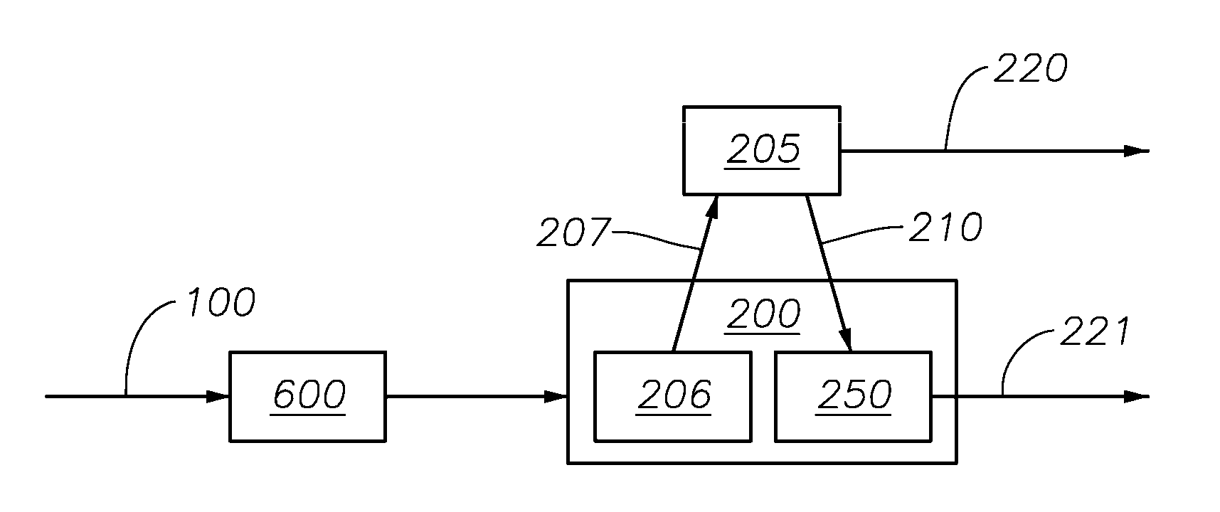
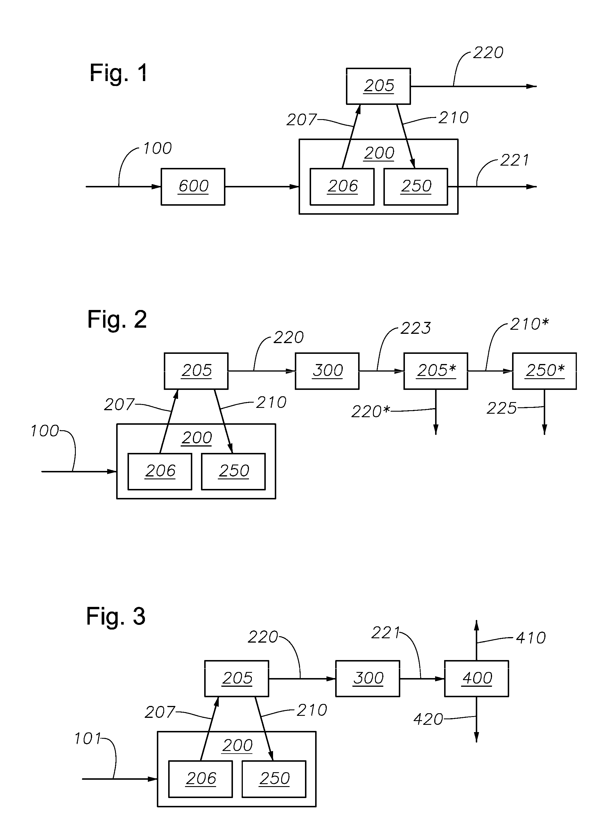
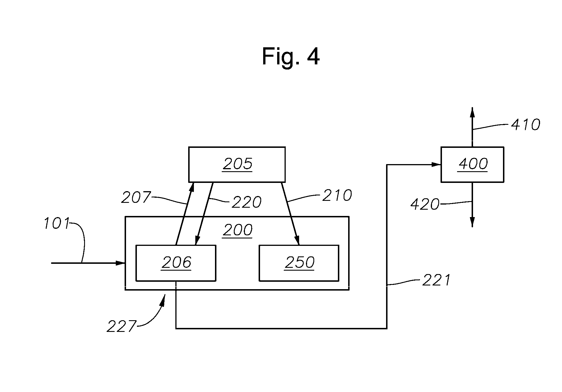
This invention relates to a process and system for cracking hydrocarbon feedstock containing vacuum resid comprising: (a) subjecting a vacuum resid to a first thermal conversion in a thermal conversion reactor (such as delayed coker, fluid coker, Flexicoker™, visbreaker and catalytic hydrovisbreaker) where at least 30 wt % of the vacuum resid is converted to material boiling below 1050° F. (566° C.); (b) introducing said thermally converted resid to a vapor / liquid separator, said separator being integrated into a steam cracking furnace, to form a vapor phase and liquid phase; (c) passing said vapor phase to the radiant furnace in said steam cracking furnace; and (d) recovering at least 30 wt % olefins from the material exiting the radiant furnace (based upon the weight of the total hydrocarbon material exiting the radiant furnace).

Description

CROSS REFERENCE TO RELATED APPLICATIONS[0001]This application is related to concurrently filed application U.S. Ser. No. 12 / 833,485, filed on Jul. 9, 2010. This application also relates to U.S. Ser. No. 12 / 692,222, filed Jan. 22, 1010.FIELD OF THE INVENTION[0002]The invention relates to a method of making olefins from a crude or resid-containing crude fraction in a steam cracking furnace or a pyrolysis furnace.BACKGROUND OF THE INVENTION[0003]Thermal cracking of hydrocarbons is a petrochemical process that is widely used to produce olefins such as ethylene, propylene, butylenes, butadiene, and aromatics such as benzene, toluene, and xylenes. Each of these is a valuable commercial product in its own right. For instance, the olefins may be oligomerized (e.g., to form lubricant basestocks), polymerized (e.g., to form polyethylene, polypropylene, and other plastics), and / or functionalized (e.g., to form acids, alcohols, aldehydes and the like), all of which have well-known intermediate ...

Claims


Application Information

Patent Timeline
Patent Type & Authority Patents(United States)
IPC IPC(8): C07C4/04
CPCC10B55/00C10B55/10C10G9/005C10G9/007C10G9/36C10G51/023B01J10/005C10G2300/1077C10G2400/20C10G2400/30C10G2300/301C10G2300/4006C10G2300/807
Inventor DAVIS, S. MARKSTELL, RICHARD C.LIOU, JIUNN-SHYANBROWN, STEPHEN H.KEUSENKOTHEN, PAUL F.DINICOLANTONIO, ARTHUR R.WALDROP, JOHN J.
Owner EXXONMOBIL CHEM PAT INC
Learn More