Ion acceleration system for medical and/or other applications

a technology of ion acceleration and medical devices, applied in the field of complex or system of particle accelerators, can solve problems such as affecting potentialities, and achieve the effects of reducing power consumption, facilitating installation in hospital centers, and reducing volum

Active Publication Date: 2013-03-26
ADVANCED ONCOTHERAPY PLC
View PDF14 Cites 97 Cited by
  • Summary
  • Abstract
  • Description
  • Claims
  • Application Information

AI Technical Summary

Benefits of technology

[0026]In cancer therapy a linac mounted on a gantry rotating around the patient is a solution which is simpler, more flexible and surer than the ones based on circular accelerators mounted on gantries. Indeed the output beam is pulsed with rates in the range 50-500 Hz and can be very easily coupled to an ‘active’ dose spreading system, since the particle energy and the dose given to a voxel can be adjusted, electronically and in about 1 millisecond, from pulse to pulse (R. Zennaro, IDRA: Design Study of a Proton Therapy Facility, Beam Dynamics Newsletter, n. 36, p. 62, April 2005). This unique property implies that there is no need for absorbers to reduce the beam energy, as in fixed-energy cyclotrons. As a consequence the unwanted production of intense and difficult to shield neutron fluxes close to the patient is avoided.
[0028]The use of the ion acceleration system for hadron therapy according to the invention presents many important advantages. First of all the accelerator is lighter with respect to existing cyclotrons and synchrotrons, and is characterized by a modular structure composed of the same high technology equipment repeated almost without variation for each accelerating module. Secondly, the proposed system is relatively compact, so minimal volumes and installation surfaces are needed, therefore facilitating the installation in hospital centers. Moreover, the high frequency of the linac allows for a reduction in power consumption which reflects in reduced exploitation costs.
[0029]In summary, with respect to the hadron therapy facility either in use or conceived, the present invention allows 1) to build compact facilities 2) having a single-room which 3) can be installed also in already existing medium sized hospitals leading so 4) to lead, due to the relatively low cost, to a wide spread diffusion of tumour hadron therapy.

Problems solved by technology

However these potentialities are hindered by the necessity of large capital investments to construct multi-room facilities.

Method used


Image

  • Ion acceleration system for medical and/or other applications
  • Ion acceleration system for medical and/or other applications
  • Ion acceleration system for medical and/or other applications

Examples


Embodiment Construction

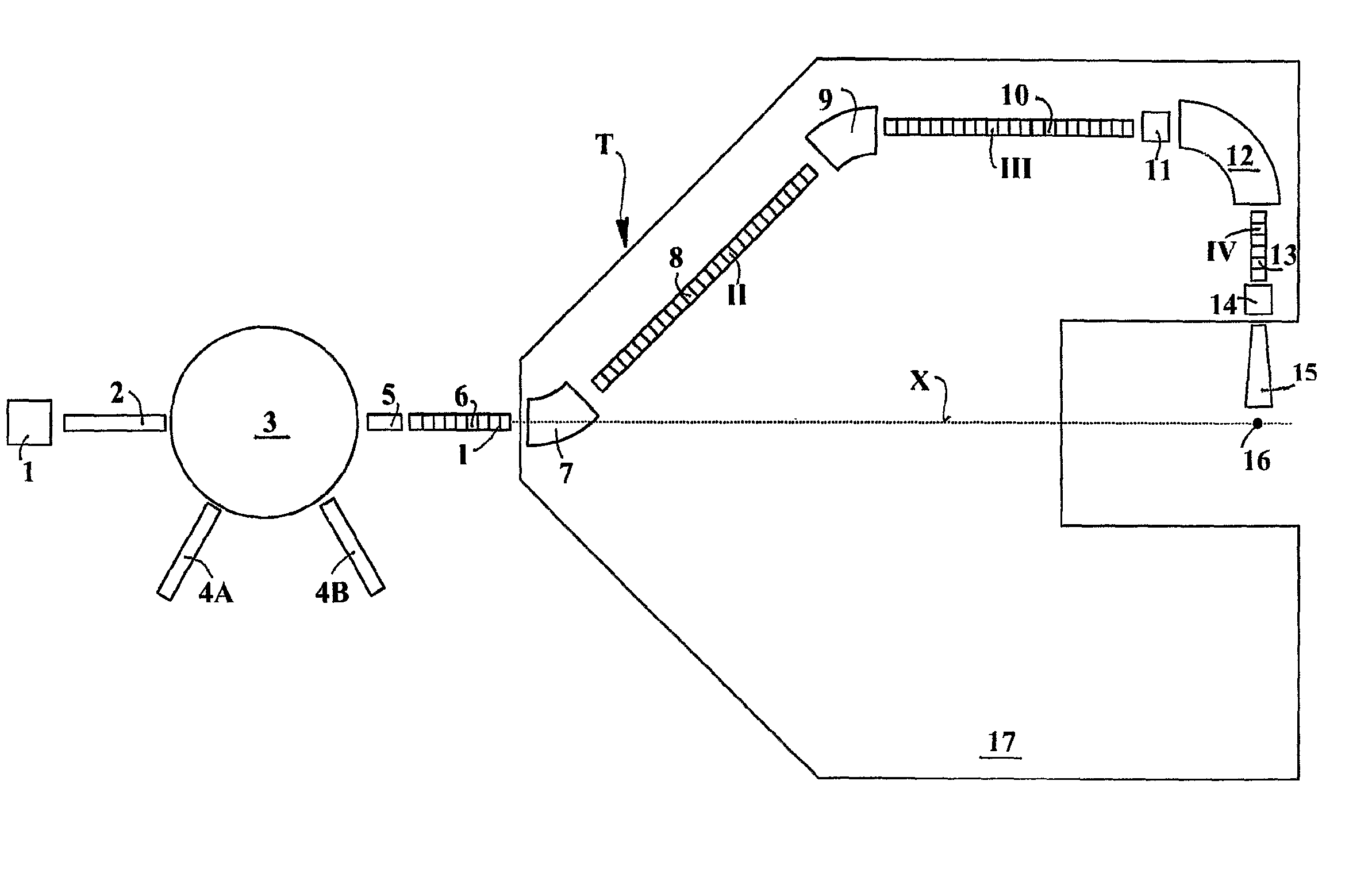
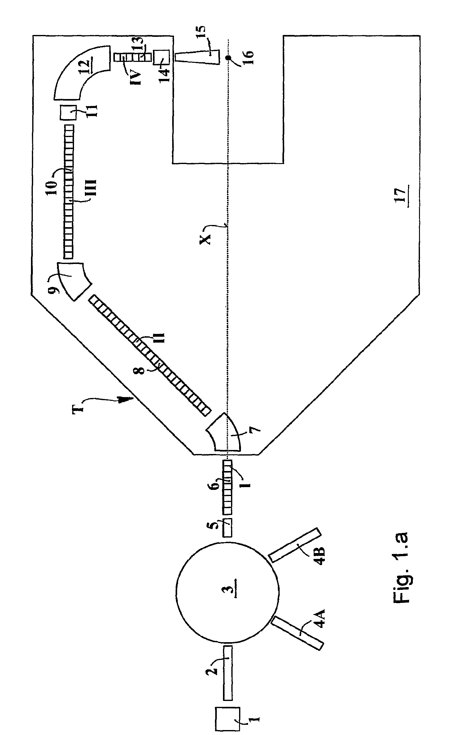
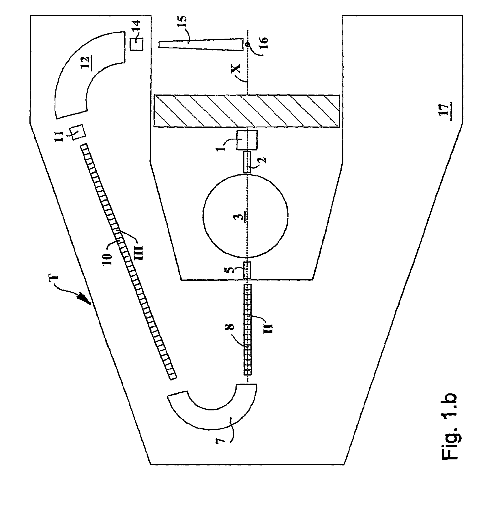
[0034]The components of the complexes T of hadron accelerators shown in FIG. 1.a, 1.b, and 1.c are the following:[0035]1. ion source;[0036]2. Low Energy Beam Transport channel (LEBT);[0037]3. cyclotron (normal or superconducting) or FFAG (normal or superconducting) or other circular accelerator;[0038]4. 4A and 4B: beams extracted from the circular accelerator 3 and used for other purposes either in parallel or alternatively with the gantry;[0039]5. Medium Energy Beam Transport channel (MEBT);[0040]6. first (I) linac section, at a frequency typically greater than 1 GHz, and beam transport magnetic channel;[0041]7. first Integrated Magnetic Transport Channel (1st IMTC) made of quadrupoles, bending magnet(s) and RF buncher(s) to transport, bend and shape the hadron beam;[0042]8. second (II) linac section with a frequency that can be a multiple of the one of the first linac section (I);[0043]9. second Integrated Magnetic Transport Channel (2nd IMCT) made of quadrupoles, bending magnet(s...


PUM


Abstract

The ion acceleration system or complex (T) for medical and / or other applications is composed in essence by an ion source (1), a pre-accelerator (3) and one or more linear accelerators or linacs (6, 8, 10, 13), at least one of which is mounted on a rotating mechanical gantry-like structure (17). The isocentrical gantry (17) is equipped with a beam delivery system, which can be either ‘active’ or ‘passive’, for medical and / or other applications. The ion source (1) and the pre-accelerator (3) can be either installed on the floor, which is connected with the gantry basement, or mounted, fully or partially, on the rotating mechanical structure (17). The output beam can vary in energy and intensity pulse-by-pulse by adjusting the radio-frequency field in the accelerating modules of the linac(s) and the beam parameters at the input of the linear accelerators.

Description

FIELD OF THE INVENTION[0001]The present invention relates to a complex or system of particle accelerators, which includes one or more linear accelerators (linacs) according to the preamble of claim 1.BACKGROUND OF THE INVENTION[0002]It is known that hadron therapy is the modern cancer teletherapy that uses beams either of protons or of heavier nuclear charged particles with mass number larger than 1.[0003]It is equally known that in protontherapy, which is a particular hadron therapy technique based on the use of proton beams, therapeutic beams of relatively low current (of the order of some nanoamperes) are used, with energies in the range 60 to 250 MeV.[0004]It is also known that, in the case of different ion species, therapeutic beams with lower currents and higher energies are required compared to the ones for the protons. For example, in the case of carbon ions 12C6+, the required energies are between 1.500 and 5.000 MeV (i.e. 120 and 450 MeV / u) and currents of a fraction of na...

Claims


Application Information

Patent Timeline
Patent Type & Authority Patents(United States)
IPC IPC(8): A61N5/01G21G5/00H05H9/00
CPCA61N5/10A61N5/1081G21K5/04G21K5/10H05H7/22H05H9/00A61N2005/1087
Inventor AMALDI, UGOBRACCINI, SAVERIOMAGRIN, GIULIOPEARCE, PETERZENNARO, RICCARDO
Owner ADVANCED ONCOTHERAPY PLC
Why Eureka
Try Eureka