Multilayer circuit substrate

a multi-layer circuit and substrate technology, applied in the direction of printed circuit aspects, printed circuit construction, electrical apparatus construction details, etc., can solve the problems of unnecessary heat dissipation and expensive resin us

Active Publication Date: 2013-04-09
JTEKT CORP
View PDF19 Cites 3 Cited by
  • Summary
  • Abstract
  • Description
  • Claims
  • Application Information

AI Technical Summary

Benefits of technology

[0010]Accordingly, it is an object of the invention to provide a multilayer circuit substrate in which an electronic component that generates a large amount of heat is not mounted on a front layer (first layer) surface and heat dissipation efficiency by thermal conduction from the electronic component to a metal substrate is increased.
[0012]With the multilayer circuit substrate according to the first aspect, the electronic component that generates a large amount of heat is mounted on the metal substrate portion, rather than the laminated circuit portion, thereby making it possible to increase heat dissipation efficiency by thermal conduction from the electronic component to the metal substrate. Furthermore, such a simple configuration makes it unnecessary to form heat dissipating via holes in the laminated circuit portion or use expensive resin having high thermal conductivity. Therefore, the production cost can be reduced.
[0014]With such a configuration, because the electronic component mounted on the metal substrate portion is disposed inside the opening of the multilayer circuit portion, for example, wire bonding from the electronic component to the laminated circuit portion can be easily performed via this opening. In addition, because such an opening can be easily formed, the production cost can be reduced. Moreover, such a configuration can reduce the substrate size.
[0016]With such a configuration, because the laminated circuit portion and metal substrate portion are screwed together or bonded with an adhesive, it is not necessary to join the laminated circuit portion to the metal substrate portion of different thermal capacity by hot-press joining and the manufacturing process is simplified. Further, with such a configuration, thermal conductivity to the heat sink attached to the multilayer circuit substrate can be prevented from being degraded by warping of the substrate during cooling after hot-press joining and sufficient heat dissipation from the heat sink can be ensured.
[0018]According to the second aspect, an electronic component that generates a large amount of heat is mounted on the heat spreader that is inserted in the first recess portion of the laminated circuit portion, rather than on the surface layer of the laminated circuit portion. As a result, heat dissipation efficiency by thermal conduction from the electronic component to the metal substrate can be greatly increased, for example, over the conventional configuration having heat dissipating via holes. Such a simple configuration makes it unnecessary to form heat-dissipating via holes of a fine structure in the multilayer circuit substrate, thereby making it possible to reduce the production cost.
[0020]According to the above-described aspect, when the laminated circuit portion is hot-press joined to the metal substrate portion, the heat spreader on which the electronic component has been mounted does not hinder the hot-press joining process. Furthermore, the electronic component is not fractured by hot-press joining and the heat spreader can be adequately hot-press joined.

Problems solved by technology

Furthermore, such a simple configuration makes it unnecessary to form heat dissipating via holes in the laminated circuit portion or use expensive resin having high thermal conductivity.

Method used


Image

  • Multilayer circuit substrate
  • Multilayer circuit substrate
  • Multilayer circuit substrate

Examples


first embodiment

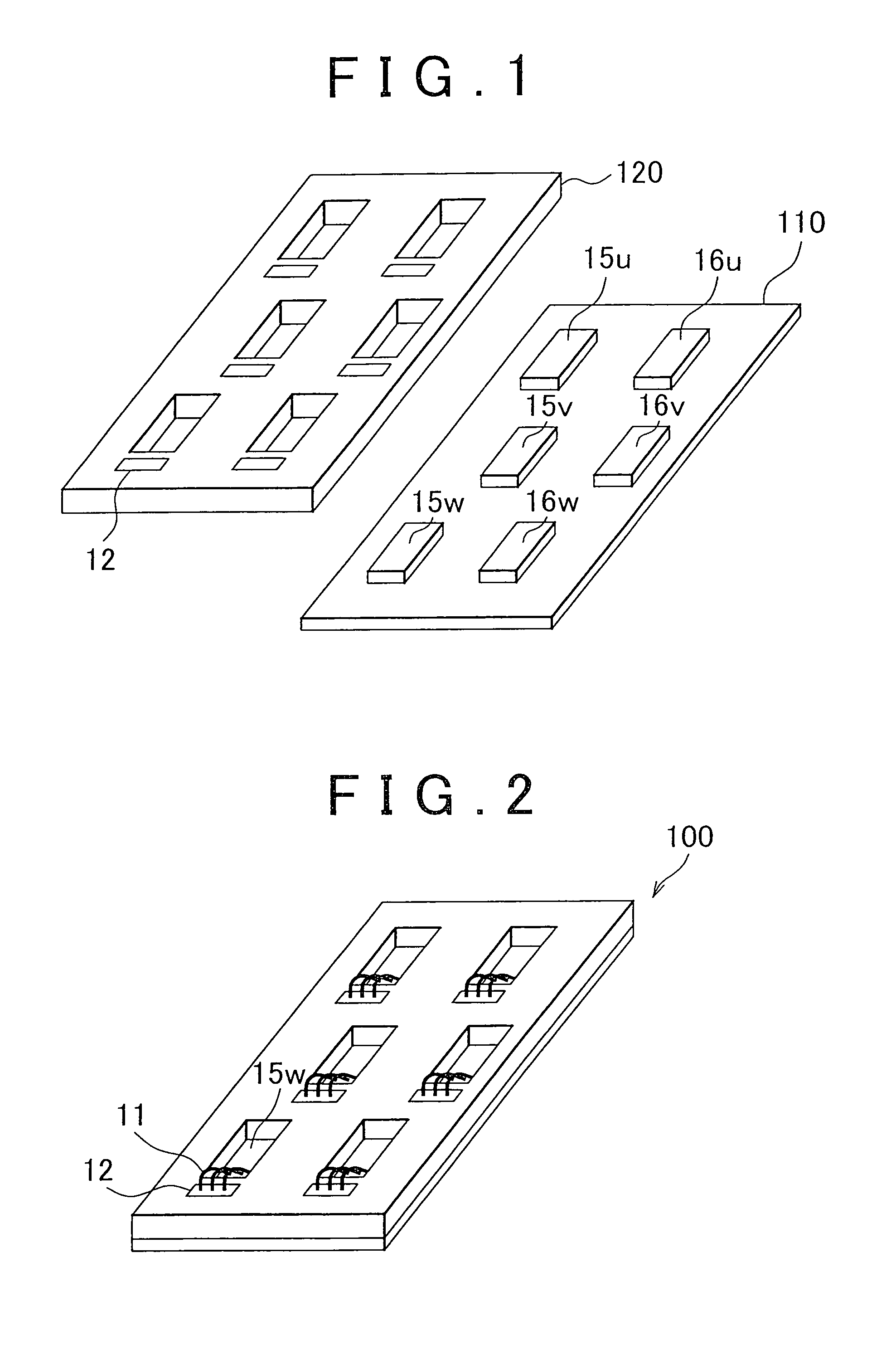
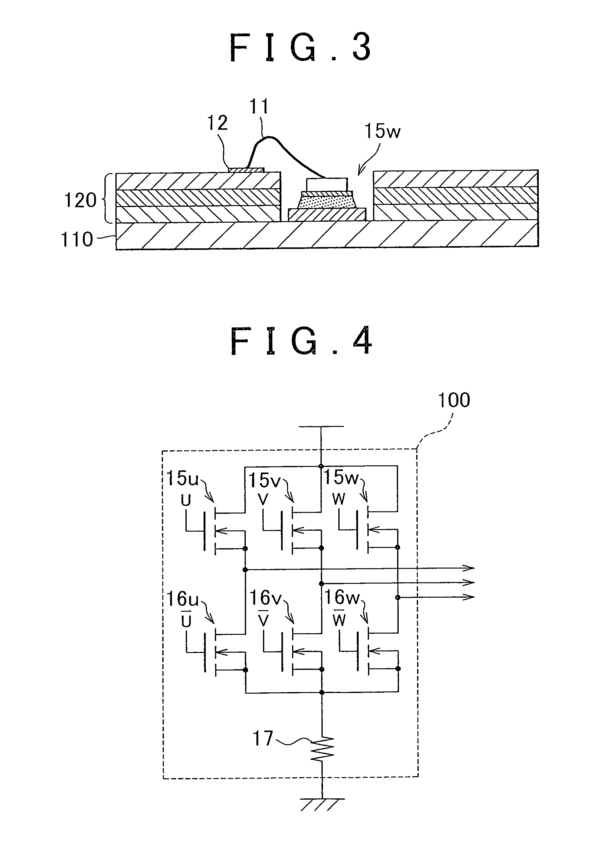
[0036]The multilayer circuit substrate is a motor drive circuit substrate for an electric power steering device, and this motor drive circuit substrate is contained and used in an ECU for an electric power steering device serving as an ECU.

[0037]The ECU includes a motor control circuit that calculates the amount of drive current that will be supplied to a steering assist motor and a motor drive circuit that controls a high current and drives the steering assist motor. In the motor control circuit, the amount of heat generated when the circuit operates is small and the current flowing therein is also small, whereas in the motor drive circuit, the amount of heat generated when the circuit operates is large and the current flowing therein is also large. Such a motor drive circuit is mounted on a motor drive circuit substrate, and the motor control circuit is mounted on a separate circuit substrate. These two circuit substrates are arranged side by side or disposed as a two-stage stack...

second embodiment

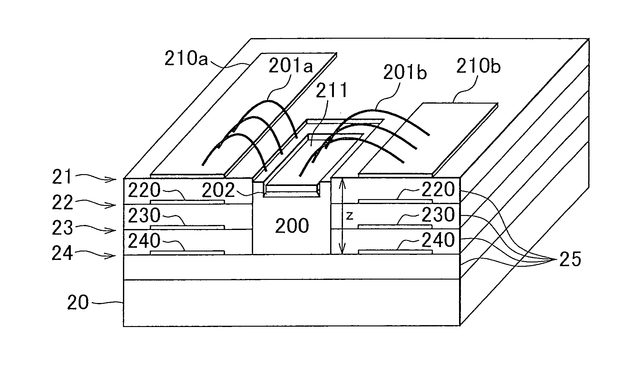
[0050]FIG. 5 is a perspective view illustrating a cross-sectional structure of each layer in the multilayer circuit substrate of the invention. FIG. 6 is an external perspective view of a heat spreader and a semiconductor element contained in the multilayer circuit substrate. FIG. 7 is a perspective view illustrating a cross-sectional structure of each layer in the multilayer circuit substrate of the related art.

[0051]The multilayer circuit substrate shown in FIG. 5 is provided with a laminated circuit portion in which conductive layers and insulating layers are alternately laminated by sandwiching insulating layers 25 between the conductive layers from the first conductive layer 21 to the fourth conductive layer 24, and a metal substrate 20 that is attached from below to the laminated circuit portion for heat dissipation.

[0052]The metal substrate (metal base) 20 is formed from a metal with a good thermal conductivity, such as aluminum, and functions as a heat sink. The metal substr...


PUM


Abstract

A multilayer circuit substrate includes: a laminated circuit portion in which conductive layers and resin insulating layers are alternately laminated; and a metal substrate portion, wherein the laminated circuit portion is fixed to the metal substrate portion so that at least part of a lower surface of the laminated circuit portion is in contact with at least part of an upper surface of the metal substrate portion. An electronic component is mounted on the metal substrate portion.

Description

INCORPORATION BY REFERENCE[0001]The disclosure of Japanese Patent Application No. 2008-237471 filed on Sep. 17, 2008 including the specification, drawings and abstract is incorporated herein by reference in its entirety.BACKGROUND OF THE INVENTION[0002]1. Field of the Invention[0003]The invention relates to a multilayer circuit substrate, and typically relates to a motor drive circuit substrate using the same for use in an electric power steering device.[0004]2. Description of the Related Art[0005]An electric power steering device for a vehicle drives a steering assist motor so as to obtain an advantageous steering assist force with respect to a steering torque applied to a steering wheel by a driver and a vehicle speed. The steering assist motor is driven by a motor drive circuit contained in an electronic control unit. When the steering assist motor is driven, the motor drive circuit controls a high power of about 500 W to 2000 W. The electronic control unit will be referred to he...

Claims


Application Information

Patent Timeline
Patent Type & Authority Patents(United States)
IPC IPC(8): H05K1/00
CPCH05K1/021H05K1/0298H05K1/182H05K3/0061H05K2201/10416H05K2203/049H01L2924/13091H01L2224/45124H01L2224/48091H01L2924/19107H05K2203/063H01L2924/30107H01L2924/3011H01L2924/00014H01L2924/00
Inventor NAGASE, SHIGEKINAKAI, MOTOOYOSHIDA, KOUYASUMASU, HIROSHIUCHIDA, NOBUHIRO
Owner JTEKT CORP
Why Eureka
Try Eureka