
Arrangement and method for magnetic determination of a linear length or a rotary angle

a linear length and rotary angle technology, applied in the direction of magnetic measurement, magnetic field measurement using galvano-magnetic devices, magnetic field controlled resistors, etc., can solve the problems of significant measurement errors, small detectable changes in magnetic field, soft-magnetic scale materials, etc., to achieve small measurement errors, simple structure, and high resolution

Active Publication Date: 2013-04-09
MEAS DEUTLAND
View PDF19 Cites 5 Cited by
  • Summary
  • Abstract
  • Description
  • Claims
  • Application Information

AI Technical Summary

Benefits of technology

The invention aims to provide better arrangements and methods for measuring magnetic length and angle with higher resolution, smaller measurement errors, and greater measurement distances.

Problems solved by technology

Disadvantageously, the material of the scale must be soft-magnetic.
Stray fields magnetize magnetic materials that can be used in practice, which may cause significant measurement errors.
With such small values, however, the detectable changes in the magnetic field are particularly small, if the sensor and scale are not separated by a minimum distance.
In addition, a necessary adjustment of auxiliary magnets for each sensor is complex.
As an additional disadvantage, manufacture of the magnetic threaded rod, in particular with a small pitch required to attain a high resolution of the length determination, is very complex.
Rotation of the scale or parts thereof must be prevented, because it directly produces measurement errors for high-resolution.
This limits the measurement accuracy, because the determined signal can be associated with a certain segment only over a limited number of segments, which diminishes the length resolution within the segment length.
The problem with absolute measurements, however, is nowhere discussed in the document and can also not be inferred from the disclosed fact pattern.
Accordingly, this document also does not provide any suggestion how absolute measuring systems for large measurement distances and a high-resolution can be designed.

Method used


Image

  • Arrangement and method for magnetic determination of a linear length or a rotary angle
  • Arrangement and method for magnetic determination of a linear length or a rotary angle
  • Arrangement and method for magnetic determination of a linear length or a rotary angle

Examples


Embodiment Construction

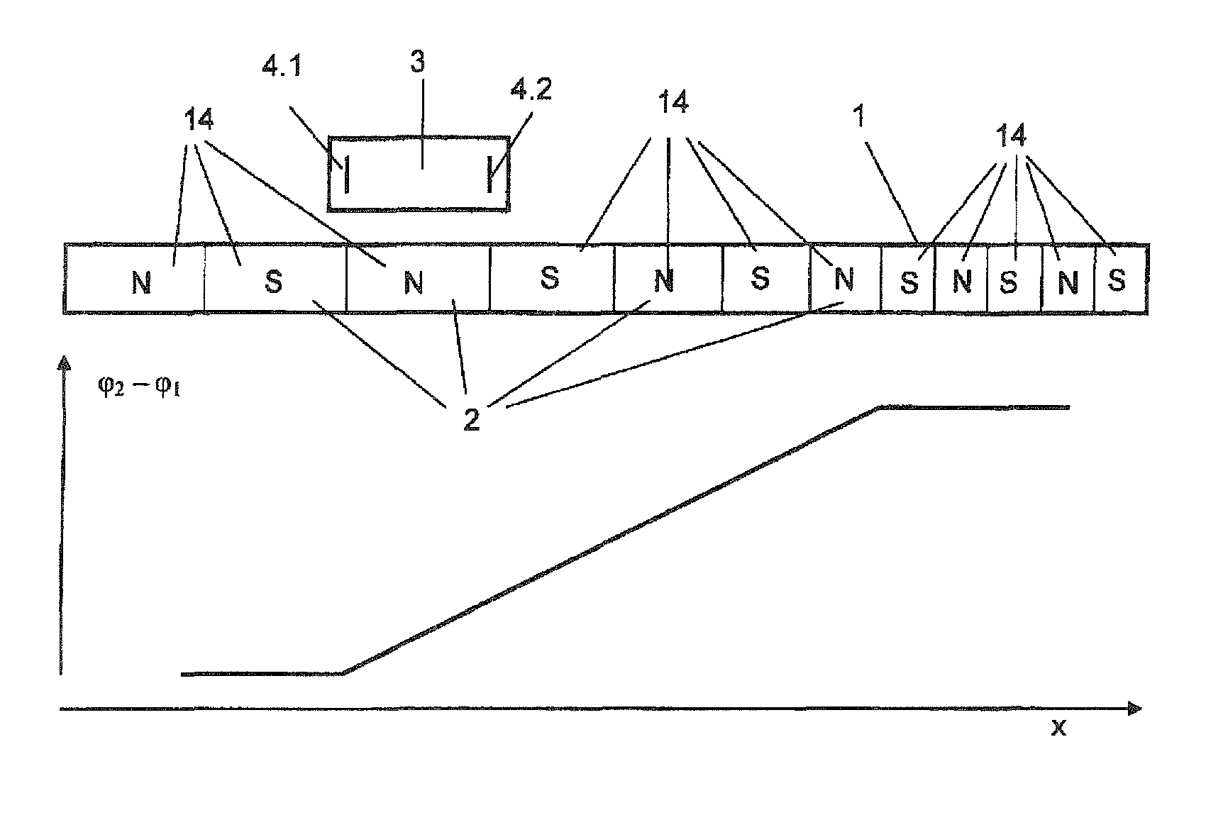
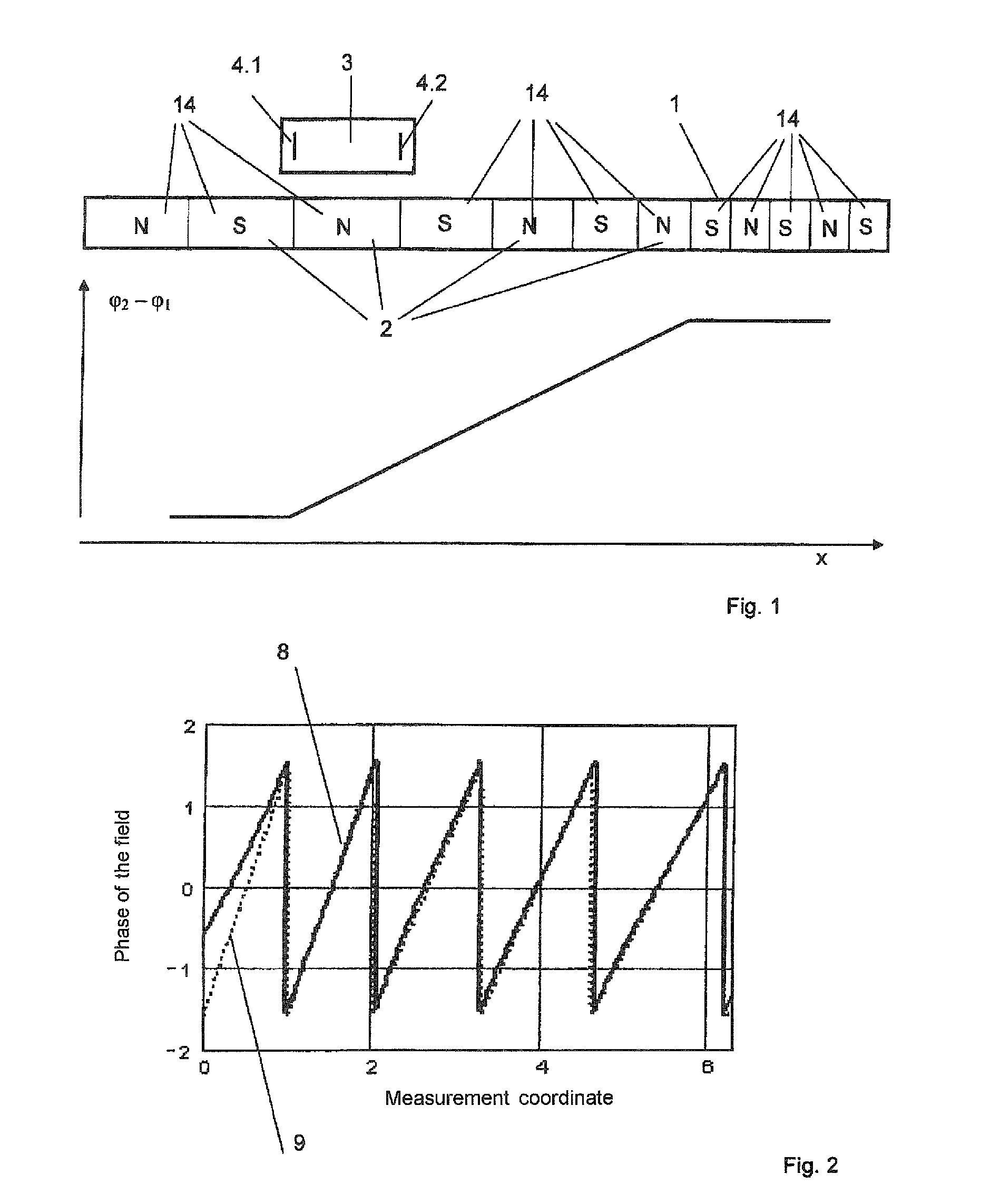
[0035]FIG. 1 shows a schematic diagram of an absolute length measuring system according to the invention and a calibration function of the system. A magnetic scale 1 is composed of a plurality of permanent magnet segments 2 which are differentiated by the symbol N (North pole) and S (South pole). This indicates that directly adjacent segments 2 are magnetized in opposite directions. A scale magnetized perpendicular to the drawing plane shows on its surface the indicated poles. However, it is assumed in the exemplary embodiment to be described below that the segments N have a magnetization direction pointing to the right and the segments S have a magnetization direction pointing to the left. The segments 2 of the scale are combined into groups 14. A first group 14 includes from the left the first three segments 2, which all have the same length in the measurement direction x. A second group 14 in the center region includes four segments 2, which have different lengths in the measurem...


PUM


Abstract

Disclosed are absolute measuring systems comprising measuring rods that are composed of groups of at least two magnetic segments. The magnetic segments of at least one group have the same length in the direction of measurement while the magnetic segments of the different groups have different lengths. For arrangements encompassing more than two sensors on the single-track measuring rods, multistage phase difference processes are disclosed which result in high resolutions and accurate measurements while allowing for great measured lengths and, when anisotropic magnetoresistive sensors are used, for example, an unambiguous angle measurement range of 360°. FIG. 6a best represents the essence of the invention.

Description

CROSS-REFERENCES TO RELATED APPLICATIONS[0001]This application is the U.S. National Stage of International Application No. PCT / EP2008 / 001375, filed Feb. 21, 2008, which designated the United States and has been published as International Publication No. WO 2008 / 001375 and which claims the priority of German Patent Application, Serial No. 10 2007 008 870.3, filed Feb. 21, 2007, pursuant to 35 U.S.C. 119(a)-(d).BACKGROUND OF THE INVENTION[0002]The invention relates to a magnetic length or angle measuring system used, for example, for automatically determining positions, lengths or angles in mechanical engineering, automotive engineering or precision mechanics. The “absolute” system provides the corresponding values independent of the movement of the system components, in particular also at rest.[0003]Such absolute magnetic length or angle measuring systems are known in the art. The measuring arrangement described in the published application DE 197 54 524 should be mentioned first. Th...

Claims


Application Information

Patent Timeline
IPC IPC(8): G01B7/14
CPCG01D5/12
Inventor BARTOS, AXELDETTMANN, FRITZMEISENBERG, ARMIN
Owner MEAS DEUTLAND
Learn More