Tower computer system

a computer system and tower technology, applied in the direction of cooling/ventilation/heating modifications, electrical apparatus casings/cabinets/drawers, instruments, etc., can solve the problems of poor heat dissipation effect, inability to improve, and power consumption equivalent to the performance capability of the same product, so as to improve the convenience of installation, reduce the length of the chassis, and increase the load carrying capacity of the chassis

Inactive Publication Date: 2013-04-09
WUXI APPTEC CO LTD WUXI PHARMATECH
View PDF7 Cites 14 Cited by
  • Summary
  • Abstract
  • Description
  • Claims
  • Application Information

AI Technical Summary

Benefits of technology

[0018]The primary object of the present invention is to provide a tower computer system having a mounting assembly of a tower chassis for facilitating users to install a motherboard vertically and divide the chassis into two back-to-back assembling chambers, so as to reduce the length of the chassis to appropriate length and height, increasing the load carrying capacity of the chassis, and improve the convenience of the installation and expansion upgrade, and using separated wind fields to improve the heat dissipation efficiency.

Problems solved by technology

As a result, products of the same stage have a power consumption equivalent to the performance capability.
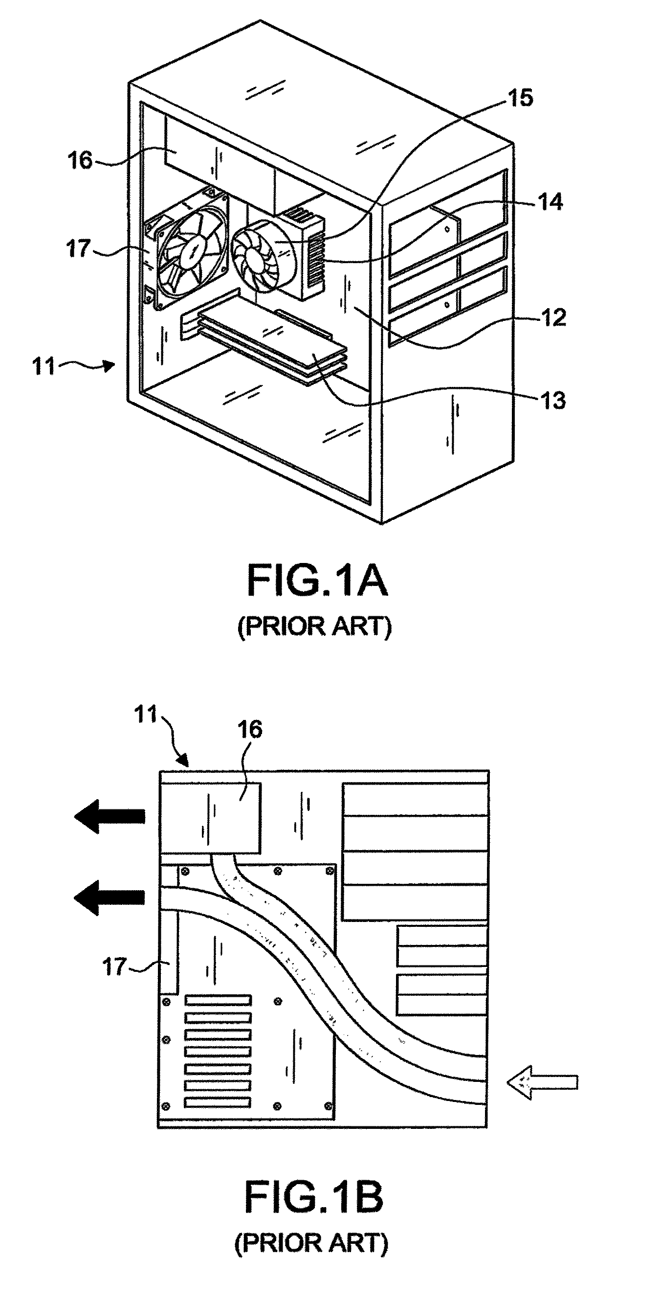
Even if there is a change to the structure of the case and the installation of components, the fan of the power supply device 16 and an additionally installed fan 17 are used for blowing air indirectly to dissipate the heat gradually, and the sequence of the heat dissipation of the system is reverse and thus resulting in a poor heat dissipation effect.
Furthermore, the internal lateral layer of the case is aligned outward, and components such as a hard disk, an optical disk drive and a support frame for installing the aforementioned components constitute many obstacles and dead corners for the ventilation.
Even with the installation of additional fans, and the use of good chip heat sinks, the heat dissipation effect cannot be improved.
In other words, despite many fans installed, most of the quantity of the wind are offset with each other and cannot be accumulated.
Furthermore, internal components and support frames for installing these components constitute many dead corners to produce a reverse pressure, and such reverse pressure will block the airflow from being spread out, exchanged and delivered.
As a result, a linear airflow cannot be achieved, and the amount of airflow corresponding to the number of fans cannot be made.
These drawbacks give rise to the short life cycle of products of the related specification and exclusively specified component modules such as the heat sinks and cases, and these products are not available in the retailed market anymore since 2006.
Although the motherboard is still situated on the internal lateral layer of the case to improve the heat dissipation effect of a chip, yet dead corners stopping airflow still exist in the case and the assembling process is inconvenient.
However, without changing the position of the motherboard installed at the internal lateral layer of the case, this technology involving a large case and many fans incurs not only a high manufacturing cost but also an excessive occupied space, causing inconvenience to its use, and creating a constriction to users.
Besides the drawback of having a too-large case, the additional installed multi-vane turbofan causes tremendous noise, and a computer user may feel like staying in the environment of a factory.
In the aforementioned methods, fans are added or increased, but the improvement or remediation is not cost-effective.
The conventional system having the drawbacks of a single wind field and a single chamber assembly has not been improved much, and the indirect heat exchange as specified in the BTX specification is still adopted, and a heat sink with sideway airflow and a lower heat dissipation effect is adopted so that a higher-performance product with larger power consumption is not allowed for collaboration.
Moreover, as the component modules are positioned in a way of being stacked one and another, the miniaturized case is restricted by fixed frames necessarily on both sides and hardly retards the operation of assembling the system.
Furthermore, the components of the case and the material of the heat sink in accordance with the Pico-BTX specification no longer have the usefulness of exchanging the component modules of the tower system.
There are other related patents such as a support frame that can be turned over and disassembled easily, but same as the aforementioned patents, these patents still have not considered the factors of the sequence of heat dissipating airflow, and the components are installed from the inside to the outside.
Even though the chip products with fans are mounted, the outwardly aligned bottom surface of the support frame results in blocking the air inlet and failing to suck cooler air into the case from the outside.
Moreover, it states that the previous computer is used as a computer only without add-on functions and thus such computer system has low economic benefit and fails to comply with the cost-effective requirements of modern people.
The horizontal computer system is used for carrying a single Pico-BTX motherboard specification, not only losing the diversified using value of the expandability of the computer product, but also inheriting the poor convection effect of the air in the conventional computer system.
As a result, the issues of ventilation, heat dissipation, installation of expanded devices and spatial volume cannot be taken care at the same time, regardless of the change, thought or innovation for the internal structure.
However, the expansion slots of the motherboard still adopts an interval of 2 cm apart from each other, and the present existing expansion cards generally have pins aligned in a direction towards the air sucking inlet of the fan, and the motherboard 13 as shown in FIG. 1A is installed at the internal lateral layer of the case, such that if the expansion cards are inserted one by one, there will be a problem of installing a thin fan.
A normal heat dissipation operation cannot be performed, and thus the conditions of using an expanded component module which is very different from the thin client computer cannot be used.

Method used


Image

  • Tower computer system
  • Tower computer system
  • Tower computer system

Examples


Embodiment Construction

[0054]With reference to FIGS. 9A, 9B and 9C for a tower computer system 20 of the present invention, the tower computer system 20 comprises the following elements:

[0055]A tower chassis 30 is a U-shaped body composed of a bottom 31, a front rack 32, and a rear rack 33, and integrally formed or connected with each aforementioned component depending on needs, wherein the difference of the tower chassis 30 and a conventional tower chassis resides on that no frame is in the way on both left and right sides of the chassis to provide an opening form for installation, and the total height H of the tower chassis 30 is greater than the width W of the front side of the tower chassis 30 without exceeding 2.1 times of the width W, that is, 2.1 W≧H>W, and the length L does not exceed 2.5 times of the width W, so as to maintain the best position of the center of gravity of the tower case.

[0056]A mounting assembly 34 is installed at a middle section of the widthwise surface W of the tower chassis 3...


PUM


Abstract

A tower computer system includes a tower chassis; a mounting assembly installed at a middle section of a widthwise surface of the tower chassis and coupled to internal sides of the front and rear racks to form a vertical connecting board for providing a longitudinally perpendicular fixing position to a predetermined board, and acting as a longitudinal corresponding line formed by connecting the front rack to the rear rack for the connecting board of the mounting assembly, such that the transverse widthwise surface of the tower chassis is separated into a first assembling chamber with an opening aligned towards the left side and a second assembling chamber with an opening aligned towards the right side; and a first electric connection port, disposed in a vertical direction on the rear rack and at a position proximate to the mounting assembly, and situated in an area inside the first assembling chamber.

Description

BACKGROUND OF THE INVENTION[0001](a) Field of the Invention[0002]The present invention relates to a tower computer system, and more particularly to a tower computer system having a chassis provided for installing a motherboard vertically at a middle section of a widthwise surface of the chassis to form separate chambers and separate wind fields.[0003](b) Description of the Related Art[0004]The effect of Moore's Law shows that the performance of products manufactured by chip manufacturing technologies is directly proportional to the power consumption and inversely proportional to the rise of temperature. As a result, products of the same stage have a power consumption equivalent to the performance capability. Main systems of computers, servers or game players composed of chip products generally come with a design of a heat sink. In addition to the requirement of blowing air from the front at a heat source (the inventor of the present invention has filed several patent applications fo...

Claims


Application Information

Patent Timeline
Patent Type & Authority Patents(United States)
IPC IPC(8): H05K7/20
CPCG06F1/184G06F1/20
Inventor CHENG, LIANG-HO
Owner WUXI APPTEC CO LTD WUXI PHARMATECH
Why Eureka
Try Eureka