Planar magnetic structure

a technology of planar magnetic structure and planar magnetic structure, which is applied in the direction of transformer/inductance details, magnetic bodies, electrical devices, etc., can solve the problems of disadvantageous use of bobbins, inability to meet the requirements of assembly cooling, so as to improve the cooling capability of the assembly and reduce the leakage inductance

Active Publication Date: 2013-05-14
DELPHI TECH IP LTD
View PDF13 Cites 11 Cited by
  • Summary
  • Abstract
  • Description
  • Claims
  • Application Information

AI Technical Summary

Benefits of technology

[0011]In accordance with the present invention, there is provided a planar magnetic device comprising a ferroelectric core, and interleaved dielectric spacers and planar metal windings aligned using a unique carrier. The carrier contains several alignment aids which act to keep each piece of the assembly in optimal alignment. These alignment aids also allow for the use of planar metal windings which have more than one turn. By implementing these improvements, the use of both central bobbins and substrates is not required, thereby lowering leakage inductance and enhancing the cooling capability of the assembly.

Problems solved by technology

This flexibility adversely affects both the alignment of the winding and the manufacturability of the assembly.
Another disadvantage in the current art is the use of a thick centrally placed dielectric bobbin, which acts as a holder for the interleaved layers while providing enhanced isolation between the primary and secondary windings by completely encompassing the primary winding, thereby addressing the creepage and clearance specifications for these devices.
The use of the bobbin is disadvantageous in two ways.
First, leakage inductance for these assemblies is relatively high because its value depends largely on the thickness of the insulating material between the primary and secondary windings of a magnetic device, and the bobbin is much thicker than the thin dielectric spacers used for interleaving with the windings outside of the bobbin.
Second, despite the high surface- to-volume ratio of these devices which normally would allow for a large heat removal capacity, removing heat from that portion of the assembly which is surrounded by the thick bobbin is difficult.
These problems are compounded when a thick substrate is employed for the primary winding in devices which require a many-turned winding.
The resulting assembly does not have creepage and clearance issues, but the over molding compound greatly increases the leakage inductance and makes heat removal problematic.
Cracking of the mold compound during thermal cycling is also a concern with this type of assembly.

Method used


Image

  • Planar magnetic structure
  • Planar magnetic structure
  • Planar magnetic structure

Examples


Embodiment Construction

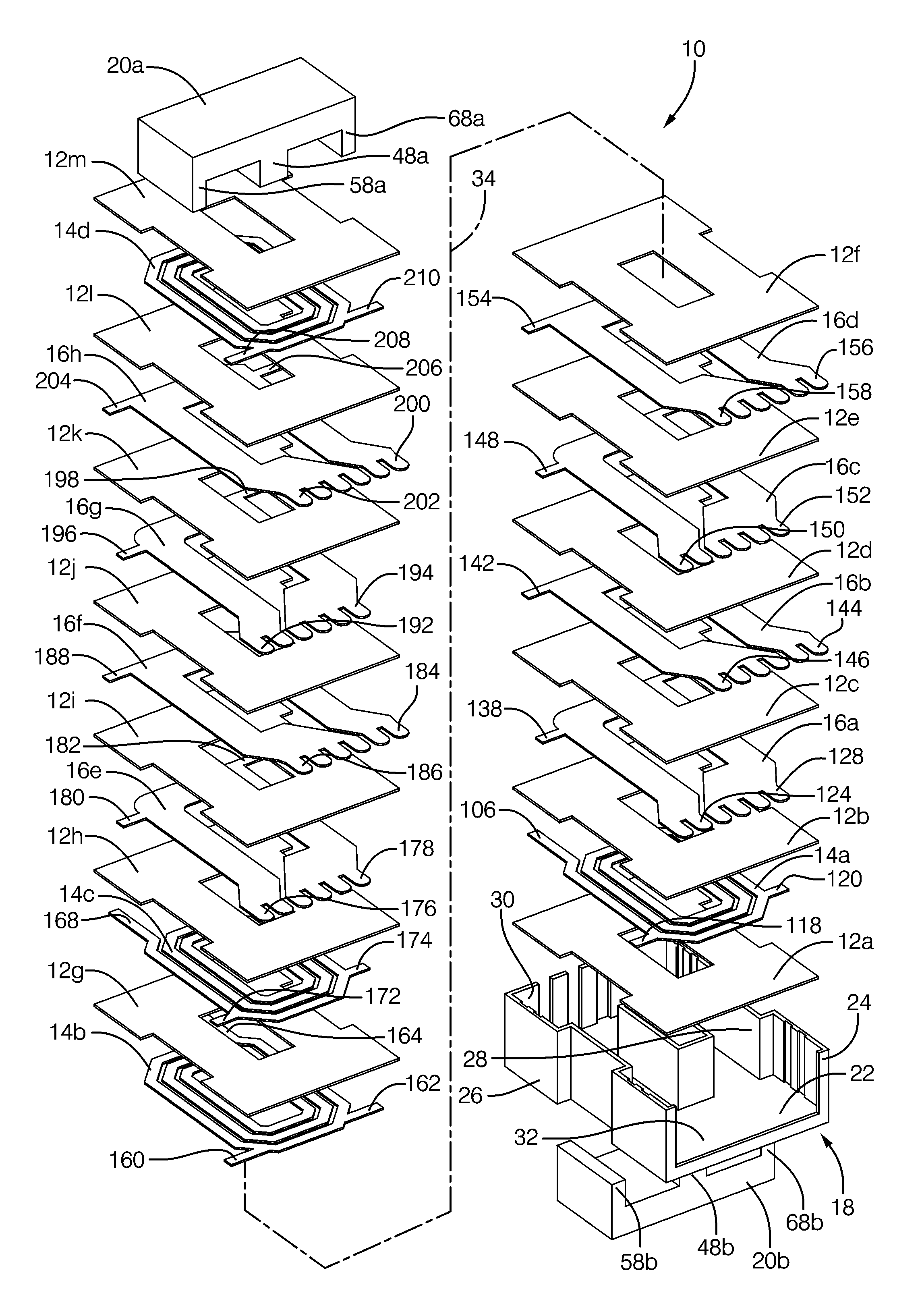
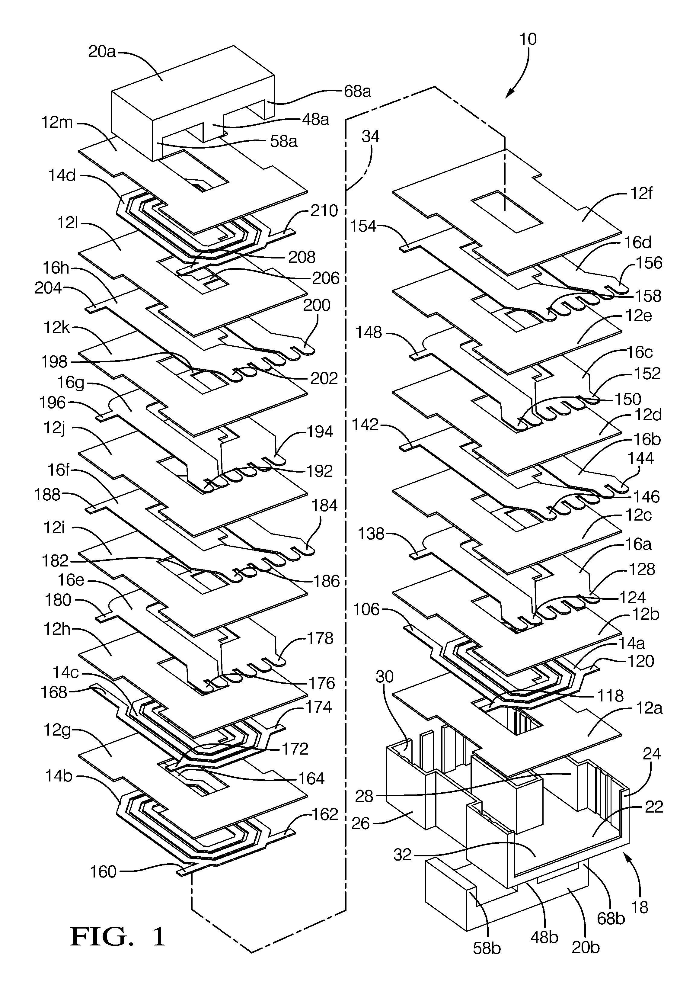
[0025]Magnetic parts generally utilize some form of coil forming structure. On large utility type of transformers they are usually called coil formers. For smaller parts they are called bobbins. In many bobbins, pins are inserted to provide an electrical termination for the magnet wire. For larger planar magnetic transformers and inductors they may be configured more like buckets. Sometimes the high voltage windings are enclosed in an envelope structure for isolation purposes. In the present invention, the term “carrier” is intended to describe all such similarly functioning structures.

[0026]One of the challenges in transformer and inductor design is to maximize the core window copper fill and, at the same time, providing the proper insulating spacing for voltage isolation. One of the more effective approaches used with large planar parts is to surround (envelop) the high voltage windings with a plastic isolator structure. This approach increases the parasitic leakage inductance by ...


PUM

PropertyMeasurementUnit
thicknessaaaaaaaaaa
creepage distanceaaaaaaaaaa
distanceaaaaaaaaaa

Abstract

A planar magnetic structure has an electrically insulating carrier made up of a base portion and opposed upstanding sidewalls. A plurality of planar primary windings and planar secondary windings are interstitially disposed within the carrier with planar dielectric spacers located between each adjacent pair of windings. A ferrite core envelopes the assembly to magnetically couple the windings. The carrier and windings form at least two spaces-apart sets of cooperating registration features which maintain the windings in fixed alignment with the carrier.

Description

TECHNICAL FIELD OF THE INVENTION[0001]The present invention relates to a method for the manufacture of planar magnetic structures and planar magnetic structures manufactured in accordance therewith.BACKGROUND OF THE INVENTION[0002]Planar magnetic structures, such as transformers, offer many advantages over traditional magnetic devices. These advantages include less weight, lower profiles, smaller footprints, design flexibility and greater efficiency.[0003]International safety standards set many of the parameters for the design of these devices. The spacing distance between primary and higher-order windings required to withstand a given working voltage is specified in terms of creepage and clearance. “Creepage” is defined as the shortest distance between two electrically active parts as measured along an insulative path. “Clearance” which is defined as the shortest distance between two electrically active parts as measured in air, must be, for instance, at least 4 mm for operating vo...

Claims


Application Information

Patent Timeline
Patent Type & Authority Patents(United States)
IPC IPC(8): H01F27/30
CPCH01F27/2847H01F27/323H01F41/00Y10T29/49075Y10T29/4902
Inventor MAPLE, ROBERT D.
Owner DELPHI TECH IP LTD
Why Eureka
Try Eureka