
Thermal shock-tolerant solid oxide fuel cell stack

a fuel cell stack and solid oxide technology, applied in the field of thermal shock-tolerant solid oxide fuel cell stacks, can solve the problems of increased mechanical stress caused by temperature changes, individual stacks of fuel cells are susceptible to damage, and fuel cells have limited tolerance for changes in temperature, so as to improve thermal shock resistance, increase overall reliability and manufacturing yield, and high efficiency electricity generation

Active Publication Date: 2013-06-04
SAINT GOBAIN CERAMICS & PLASTICS INC
View PDF18 Cites 9 Cited by
  • Summary
  • Abstract
  • Description
  • Claims
  • Application Information

AI Technical Summary

Benefits of technology

[0011]An advantage of this invention is that solid oxide fuel cell stacks of the invention have improved thermal shock resistance. The bond layers of this invention provide compliance in an otherwise rigid stack. In addition, the concept of making subassemblies that are bonded enables inspection and removal of defective subassemblies prior to stack assembly and operation, thus increasing overall reliability and manufacturing yield.
[0012]The present invention can be used in a solid oxide fuel cell (SOFC) system. SOFCs offer the potential of high efficiency electricity generation, with low emissions and low noise operation. They are also seen as offering a favorable combination of electrical efficiency, co-generation efficiency and fuel processing simplicity. One example of a use for SOFCs is in a home or other building. The SOFC can use the same fuel that is used to heat the home, such as natural gas. The SOFC system can run for extended periods of time to generate electricity to power the home and if excess amounts are generated, the excess can be sold to the electric grid. Also, the heat generated in the SOFC system can be used to provide hot water for the home. SOFCs can be particularly useful in areas where electric service is unreliable or non-existent.

Problems solved by technology

However, stacks of individual fuel cells can be susceptible to damage caused by fluctuation in temperature during their formation or use.
As a consequence, fuel cells have limited tolerance for changes in temperature.
Problems associated with mechanical stress caused by changes in temperature are exacerbated when individual fuel cells are stacked.
Limited thermal shock resistance of fuel cells, particularly of fuel cells assembled in stacks, limits the yield of production and poses a heightened risk of failure during operation.

Method used


Image

  • Thermal shock-tolerant solid oxide fuel cell stack
  • Thermal shock-tolerant solid oxide fuel cell stack
  • Thermal shock-tolerant solid oxide fuel cell stack

Examples


Embodiment Construction

[0016]The foregoing will be apparent from the following more particular description of example embodiments of the invention, as illustrated in the accompanying drawings in which like reference characters refer to the same parts throughout the different views. The drawings are not necessarily to scale, emphasis instead being placed upon illustrating embodiments of the present invention. The teachings of all patents, published applications and references cited herein are incorporated by reference in their entirety.

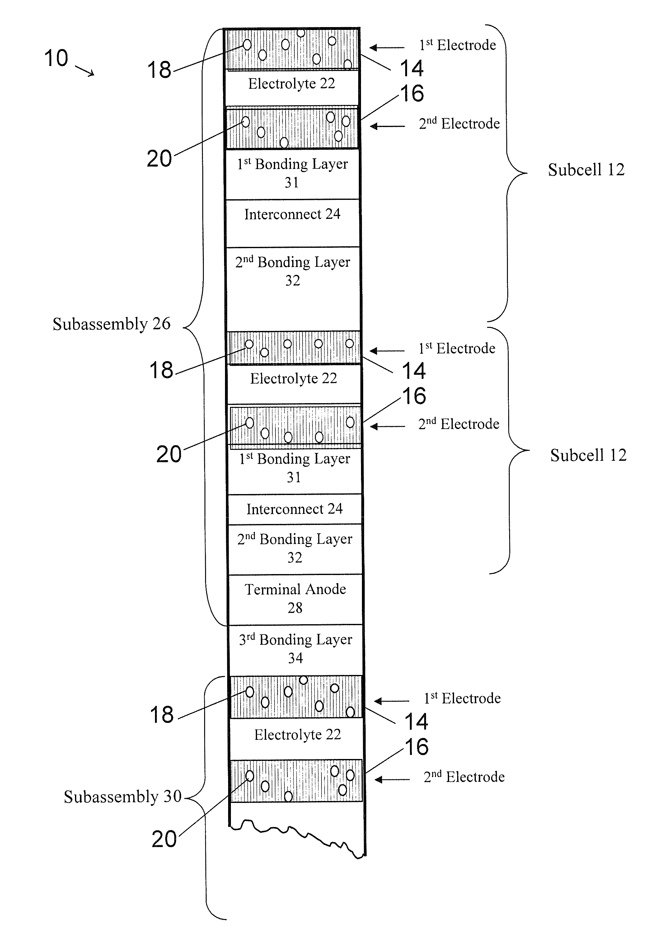
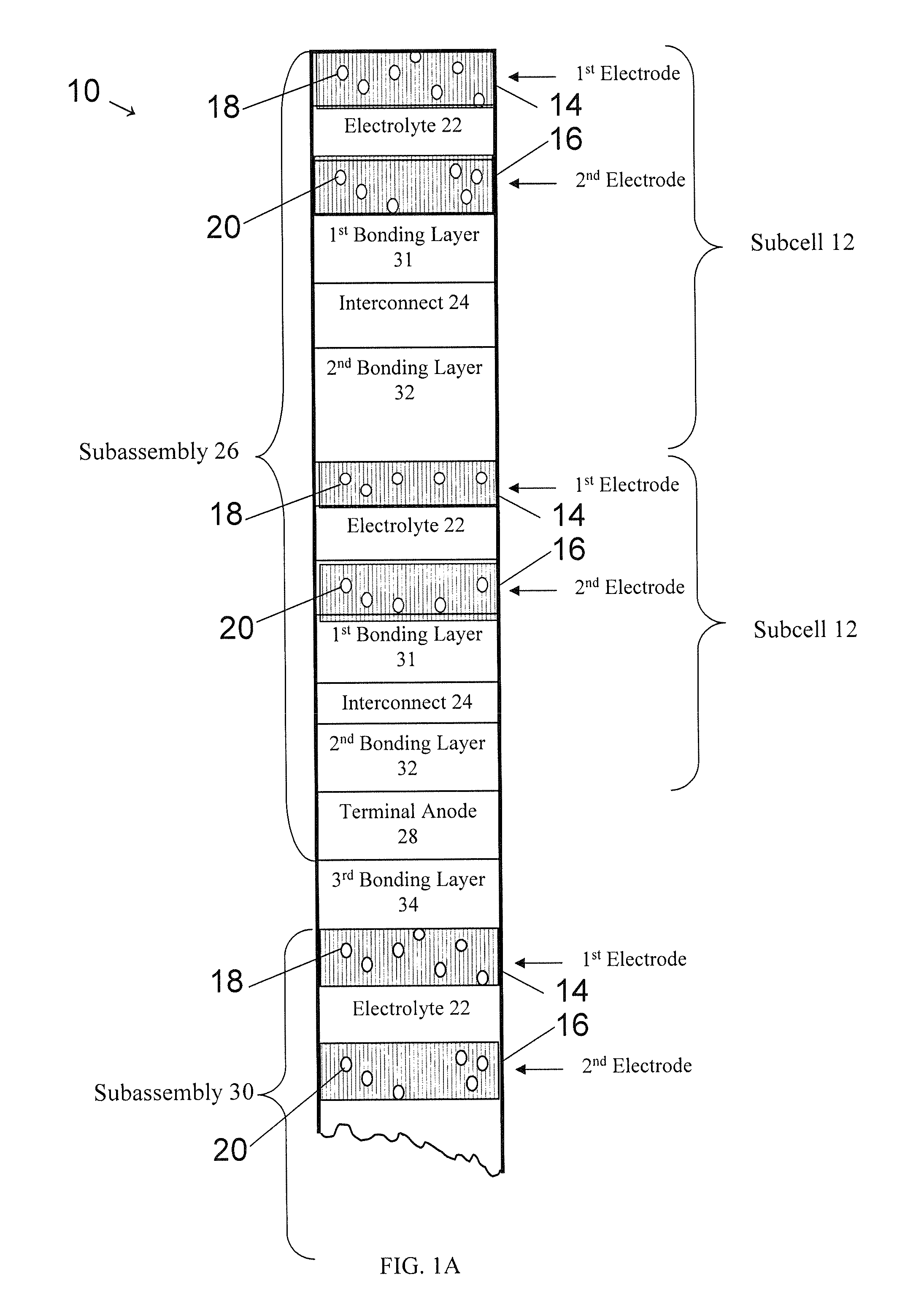
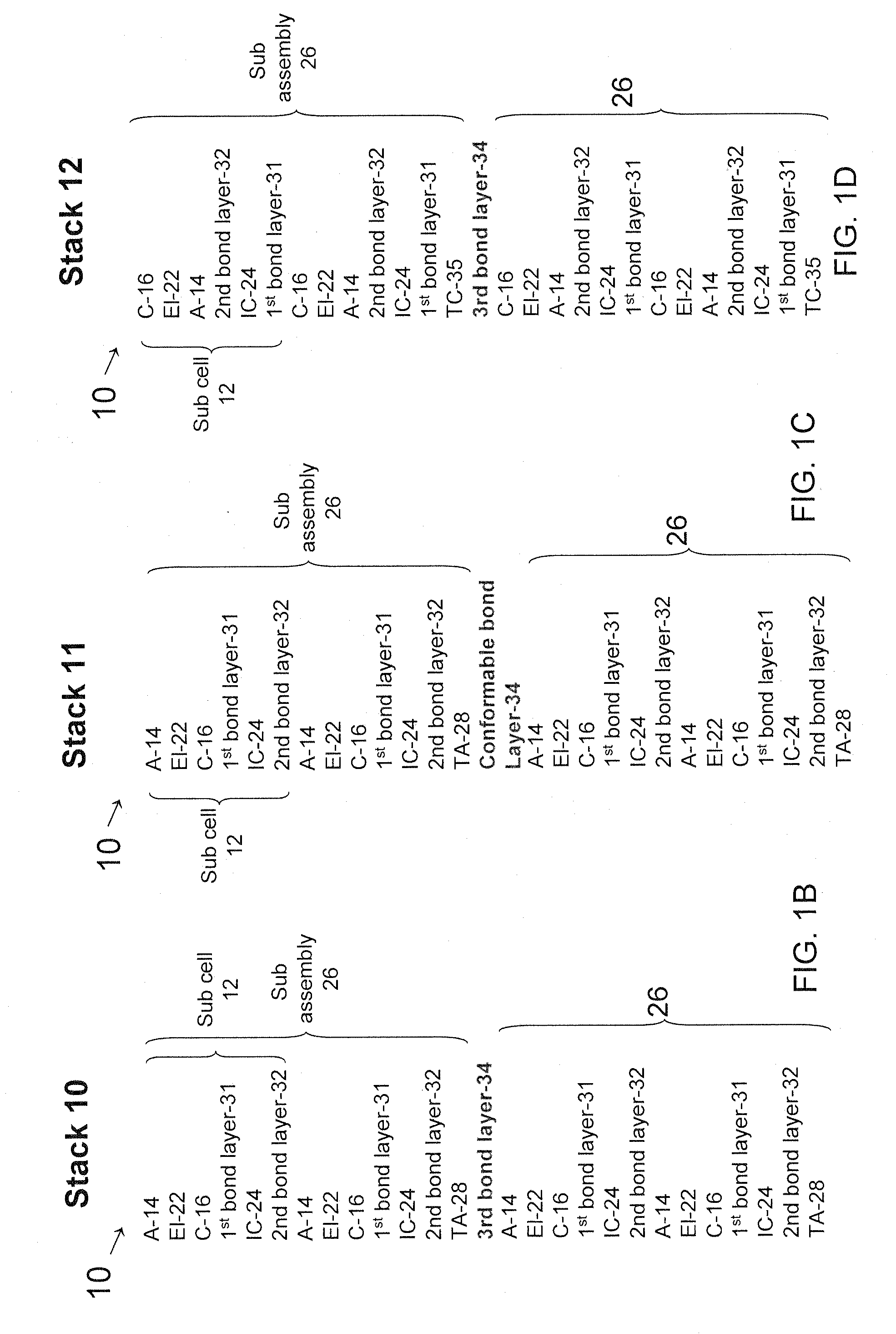
[0017]FIGS. 1A-D show fuel cell 10 of the invention. Fuel cell 10 includes a plurality of subcells 12 and each subcell 12 includes first electrode 14 and second electrode 16. Typically, first and second electrodes 14 and 16 are porous. In fuel cell 10, first electrode 14 at least in part defines the plurality of first gas channels 18 in fluid communication with a fuel gas source, such as hydrogen (H2) gas or natural gas which can be converted to H2 gas in situ at first elect...


PUM

PropertyMeasurementUnit
temperatureaaaaaaaaaa
molar ratioaaaaaaaaaa

Abstract

A solid oxide fuel cell (SOFC) includes a plurality of subassemblies. Each subassembly includes at least one subcell of a first electrode, a second electrode and an electrolyte between the first and second electrodes. A first bonding layer is at the second electrode and an interconnect layer is at the first bonding layer distal to the electrolyte. A second bonding layer that is compositionally distinct from the first bonding layer is at the interconnect layer, whereby the interconnect partitions the first and second bonding layers. A method of fabricating a fuel cell assembly includes co-firing at least two subassemblies using a third bonding layer that is microstructurally or compositionally distinct from the second bonding layer.

Description

RELATED APPLICATION[0001]This application claims the benefit of U.S. Provisional Application No. 61 / 204,035, filed on Dec. 31, 2008.[0002]The entire teachings of the above application are incorporated herein by reference.BACKGROUND OF THE INVENTION[0003]A fuel cell is a device that generates electricity by a chemical reaction. Among various fuel cells, solid oxide fuel cells use a hard, ceramic compound metal (e.g., calcium or zirconium) oxide as an electrolyte. Typically, in solid oxide fuel cells, an oxygen gas, such as O2, is reduced to oxygen ions (O2−) at the cathode, and a fuel gas, such as H2 gas, is oxidized with the oxygen ions to form water at the anode.[0004]Recently, fuel cells have been designed as stacks, whereby subassemblies, each including a cathode, an anode and a solid electrolyte between the cathode and the anode, are assembled in series by locating an electrical interconnect between the cathode of one subassembly and the anode of another.[0005]However, stacks of...

Claims


Application Information

Patent Timeline
Patent Type & Authority Patents(United States)
IPC IPC(8): H01M2/08
CPCH01M4/9033H01M8/0217H01M8/1253H01M8/0297Y02E60/525Y02E60/521Y02E60/50Y02P70/50H01M8/0258H01M8/243H01M8/2432H01M8/2457C01F17/00C01G53/00H01M8/02
Inventor KWON, OH-HUNNARENDAR, YESHWANTHKAPOOR, RAKESH
Owner SAINT GOBAIN CERAMICS & PLASTICS INC
Learn More