Retractable composite rotor blade assembly

a composite rotor blade and rotor blade technology, applied in the field of aerospace, can solve the problems of inability to provide the required compactability of the rotor blade, inability to adjust the rotor blade, and inability to meet the requirements of aerodynamic stability, and achieve the effect of convenient modification

Inactive Publication Date: 2013-06-11
CARABALLOSO ESTEBAN A +1
View PDF10 Cites 12 Cited by
  • Summary
  • Abstract
  • Description
  • Claims
  • Application Information

AI Technical Summary

Benefits of technology

[0009]In accordance with preferred embodiments of the invention, a retractable composite impeller (rotor blade) assembly is described herein. The primary difference between the present invention and the related art is that conventional rotor blades and rotor blade assemblies have longitudinally rigid blades. Furthermore, unlike telescopically retracted systems, the present invention does not require each subsequent section of the rotor blade to be of a different dimension than the preceding one. The present invention also does not restrict the length of the rotor blade. The current invention allows for controlled dynamic deployment of rotor blades. The present invention also increases the speed and precision with which the rotor blades can be retracted and deployed. The present invention makes it possible to make retractable fan blades.
[0011]Due to improvements made in the area of composite materials, the present invention employs these materials to create retractable rotor blades which do not require manual manipulation or removal of any part of the rotor blade assembly (also referred to herein as a rotor system) in order to work. By using flexible and strong composite materials to bear the primary stresses during operation, the present invention reduces the loads experienced by the remaining rigid support structure and consequently reduces the amount of creep experienced by the rotor system. Composite materials are exceptionally well suited at resisting tensile stresses and as such are ideal materials for this application. Typical composite materials include, but are not limited to, carbon and glass fibers, elastomers, aramids and other high strength polymers. Another advantage of the rotor blades of the present invention is its ability to be refitted or refurbished with very little modification and limited part replacement. In other words, if the exterior layers of the present invention are damaged they can be easily replaced without needing to replace the entire rotor system and at a considerably lower cost than conventional rotor blades.
[0014]The purpose of the blade base is to connect the rotor hub to the interlink base assembly. In one possible embodiment of the invention, the purpose of the interlink base assembly is to form a rigid structure over which the flexible sleeve can be fitted. In a second possible embodiment of the invention, the interlink base assembly is also fitted with a plurality of the helically wound ribbons. The purpose of the helically wound ribbon is to reinforce the interlink base assembly and form a rigid structure over which the flexible sleeve can be fitted. Another purpose for the helically wound ribbon is to constrict, lock and rigidify the interlink base assembly when it is in use and allow the interlink base assembly to retract when not in use.
[0016]In another possible embodiment of the invention, the flexible sleeve comprises elastic ribs, an elastic and flexible skin and an elastic sling membrane. In a second possible embodiment of the invention, the flexible sleeve can include a resealable elastic trailing edge. The purpose of the flexible sleeve is to be the outer most layer of the rotor blade assembly and, as such, it is exposed to the airstream. The flexible sleeve also serves to reinforce the rotor blade assembly and provide a smooth exterior surface for the rotor blade assembly. The flexible sleeve may be constructed of woven, braided or elastomeric material to form a covering for the cross sections and mechanical linkages of the interlink base assembly. In a second embodiment of the invention, with the use of the elastic trailing edge the rotor blade assembly is equipped with an extendable zipper mechanism. The purpose of the extendable zipper mechanism is to separate and also to reseal an upper and a lower section of the elastic trailing edge. The purpose of the blade base casing is to house the rotor blade assembly when stowed. It is to be understood that the present invention can also be used to form a wing, that is to say, it can be easily modified to be used as a wing of an airplane.

Problems solved by technology

This reduction of dimension and nonuniformity of the blade sections creates aerodynamic instabilities and it is not desirable.
These designs are too cumbersome and do not provide the required compactability of the rotor blades to be used practically by road worthy vehicles.

Method used


Image

  • Retractable composite rotor blade assembly
  • Retractable composite rotor blade assembly
  • Retractable composite rotor blade assembly

Examples


Embodiment Construction

[0057]A technical description of the major subassemblies of the invention will follow.

Rotor Blades

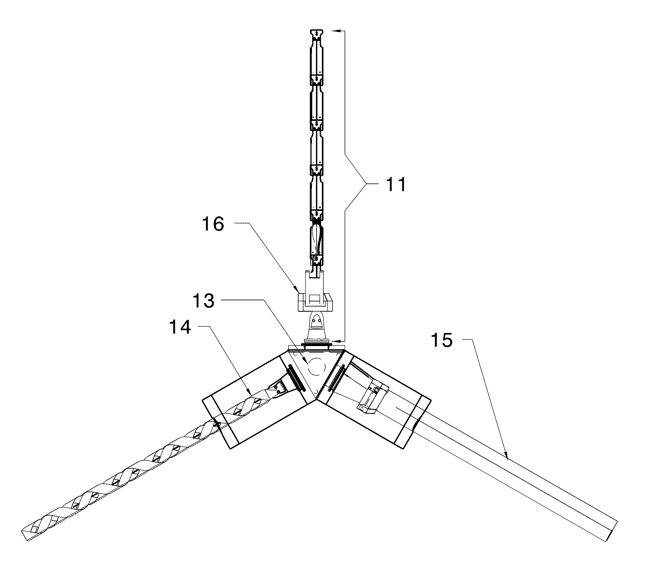
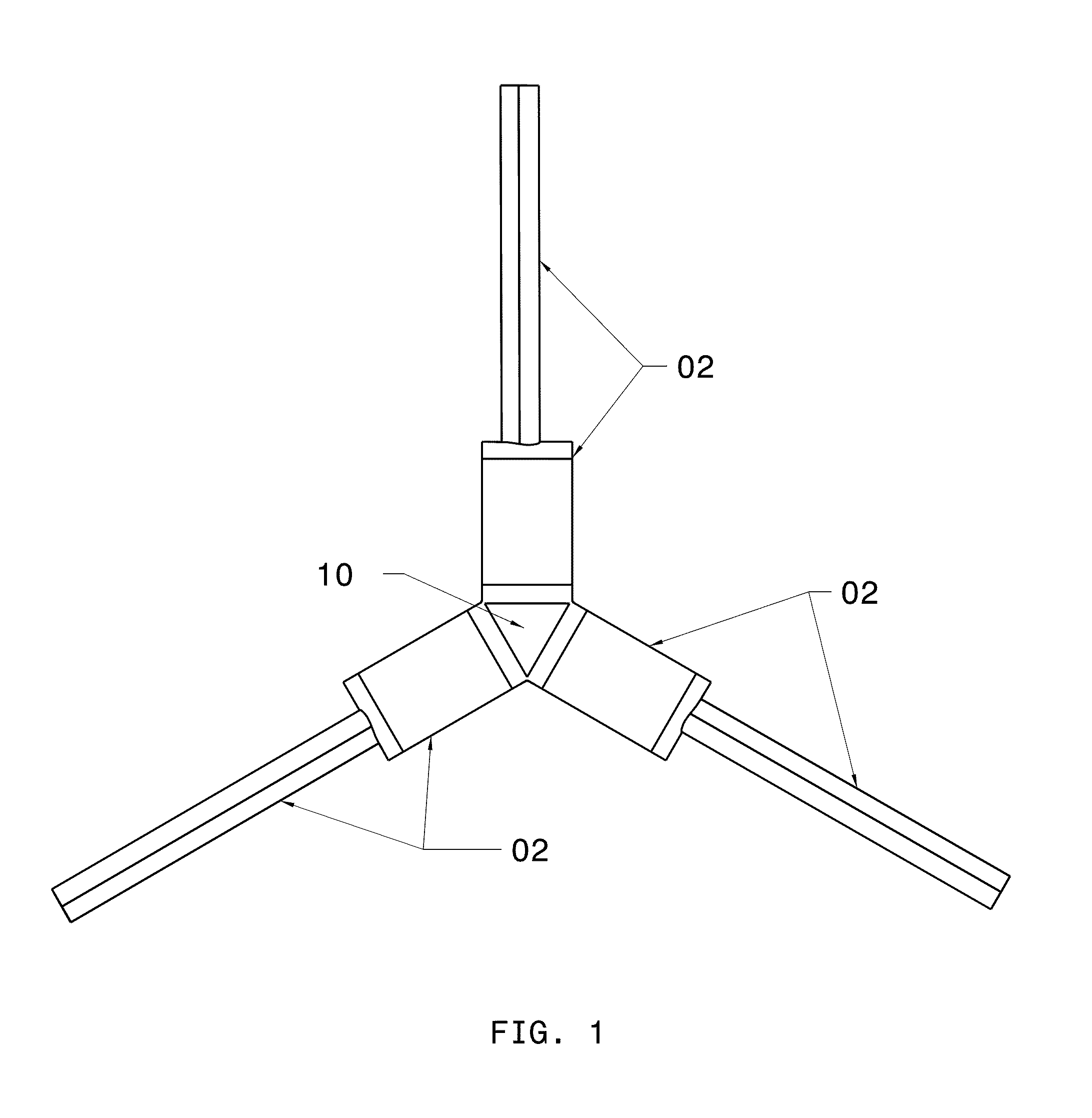
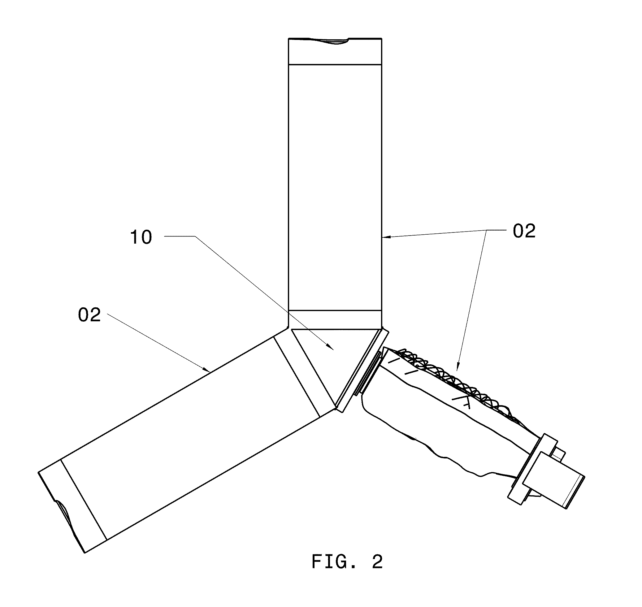
[0058]Referring to FIG. 1 and FIG. 2, the retractable composite impeller (rotor blade) assembly embodiment comprises a plurality of rotor blades 02 (three in this embodiment) as depicted. FIG. 1 also shows the retractable composite rotor blade assembly of a first preferred embodiment comprising the major subassemblies and in its fully extended condition. The geometry of a rotor hub assembly 10 corresponds to the number of rotor blades 02. In this configuration, each rotor blade assembly 02 experiences the same centripetal force during rotation and deceleration.

[0059]Referring to FIG. 1 thru FIG. 4, the major subassemblies of the rotor blade assembly of the present invention work in concert to allow each rotor blade 02 to have the ability to become extended when the rotor system is rotated, and contracted when the rotor system is forced to come to rest and in a controlled manner by way o...


PUM


Abstract

A retractable rotor blade for a flying vehicle includes an interlink assembly having interconnected link base subassemblies, a helical ribbon assembly reinforcing the interlink assembly, and a flexible and elastic sleeve that covers the interlink and helical ribbon assemblies in extended and retracted states of the rotor blade. Each link base subassembly has a damper for dampening movement of the interlink assembly during extension and retraction of the rotor blade, a pair of retractable links by which the link base subassembly is interconnected with another of the link base subassemblies, a link hub, and a pair of locking arms housed in the link hub for locking the rotor blade in the extended state. The helical ribbon assembly has sequentially overlapped ribbons helically wound around the interlink assembly. The flexible and elastic sleeve has a flexible and elastic skin and elastic ribs for imparting rigidity to the flexible and elastic skin.

Description

CROSS-REFERENCE TO RELATED APPLICATIONS[0001]This application claims priority on U.S. Provisional Patent Application No. 61 / 108,282, filed Oct. 24, 2008, which is also incorporated here by reference.BACKGROUND OF THE INVENTION[0002]1. Field of the Invention[0003]The present invention relates primarily to the field of aerospace and the field of lift generating structures. More specifically, the invention relates to the design of retractable rotor blades for a rotor blade assembly used to produce lift and thrust for vertical and short take off vehicles.[0004]2. Description of the Related Art[0005]Rotor blades have been used for many years to achieve flight. A shortcoming of the related art is that conventional rotor blades and rotor blade assemblies have longitudinally rigid structures (U.S. Pat. No. 7,475,847). Many rotor blades are now made of carbon fiber, fiber glass and other composite materials. These conventional composite rotor blades and composite rotor blade assemblies are m...

Claims


Application Information

Patent Timeline
Patent Type & Authority Patents(United States)
IPC IPC(8): B64C11/28
CPCB64C27/46B64C11/28B64C27/50B64C2027/4736B64C27/473B64C27/51F05D2250/90
Inventor CARABALLOSO, ESTEBAN A.SADEGH, ALI M.
Owner CARABALLOSO ESTEBAN A
Why Eureka
Try Eureka