Method and system for producing metallic iron nuggets

a technology of metallic iron and nuggets, applied in the field of reduction iron bearing materials, can solve the problems of increased energy consumption, undesirable metallic iron nuggets made by direct reduction, and high sulfur content of nuggets, and achieve the effects of low oxygen content, low gangue, and low porosity

Active Publication Date: 2013-06-25
NU IRON TECH LLC
View PDF45 Cites 0 Cited by
  • Summary
  • Abstract
  • Description
  • Claims
  • Application Information

AI Technical Summary

Benefits of technology

[0009]Unlike conventional direct reduced iron (DRI), these metallic iron nuggets have low oxygen content because they are metallic iron and have little or no porosity. These metallic iron nuggets are also low in gangue because silicon dioxide has been removed as slag. Such metallic iron nuggets are desirable in many circumstances such as use in place of scrap in electric arc furnaces. These metallic iron nuggets can be also produced from beneficiated taconite iron ore, which may contain 30% oxygen and 5% gangue. As a result, with such metallic iron nuggets, there is less weight to transport than with beneficiated taconite pellets and DRI, as well as a lower rate of oxidation and a lower porosity than DRI. In addition, generally, such metallic iron nuggets are just as easy to handle as taconite pellets and DRI.
[0010]Various types of hearth furnaces have been described and used for direct reduction of metallic iron nuggets. One type of hearth furnace, referred to as a rotary hearth furnace (RHF), has been used as a furnace for coal-based direct reduction. Typically, the rotary hearth furnace has an annular hearth partitioned into a preheating zone, a reduction zone, a fusion zone, and a cooling zone, between the supply location and the discharge location of the furnace. The annular hearth is supported in the furnace to move rotationally. In operation, raw reducible material comprising a mixture of iron ore and reducing material is charged onto the annular hearth and provided to the preheat zone. After preheating, through rotation, the iron ore mixture on the hearth is moved to the reduction zone where the iron ore is reduced in the presence of the reducing material and fused into metallic iron nuggets, using one or more heat sources (e.g., gas burners). The reduced and fused product, after completion of the reduction process, is cooled in the cooling zone on the rotating hearth, preventing oxidation and facilitating discharge from the furnace.
[0015]Attempts have been made to form metallic iron nuggets with low sulfur content in these previous direct reduction processes using large amounts of additives containing MgCO3 or MgO. Problems, such as increased energy consumption and increased refractory wear, have occurred with fusing these nuggets due to the increases in slag melting temperature caused by MgO in the slag. See EP 1 605 067.
[0019]In addition or in the alternative, the discrete particles of the hearth layer may have a particle size less than 4 mesh, and in some embodiments a particle size between 100 and 20 mesh or 6 mesh. Particle sizes less than 100 mesh should be avoided because these particles sizes tend to have more ash content. The thickness and particle size of the carbonaceous and other material in the hearth layer should be selected so that the hearth layer protects the hearth refractory from slag and molten metal formed during reduction of the reducible mixture, while avoiding production of excess ash. The hearth layer may have a particle size between a range of −6 to −20 mesh to a range of +65 to +150 mesh. The carbonaceous material in the reducible mixture is also different in particle size from those of the coarse overlayer, but for the different considerations. In the reducible mixture a consideration is the surface area for rapid reaction of the carbonaceous material with the reducible iron bearing material in commercial production. Less than 65 mesh or less than 100 mesh particle size of carbonaceous material in the reducible mixture is effective for efficient reduction of the iron oxide to produce metallic iron nuggets.

Problems solved by technology

A particular problem with the metallic iron nuggets formed by these previous direct reduction processes was the sulfur content of the nuggets.
This high level of sulfur has made the metallic iron nuggets made by direct reduction undesirable in many steelmaking processes, and particularly in the electric arc furnace processes.
Problems, such as increased energy consumption and increased refractory wear, have occurred with fusing these nuggets due to the increases in slag melting temperature caused by MgO in the slag.

Method used


Image

  • Method and system for producing metallic iron nuggets
  • Method and system for producing metallic iron nuggets
  • Method and system for producing metallic iron nuggets

Examples


Embodiment Construction

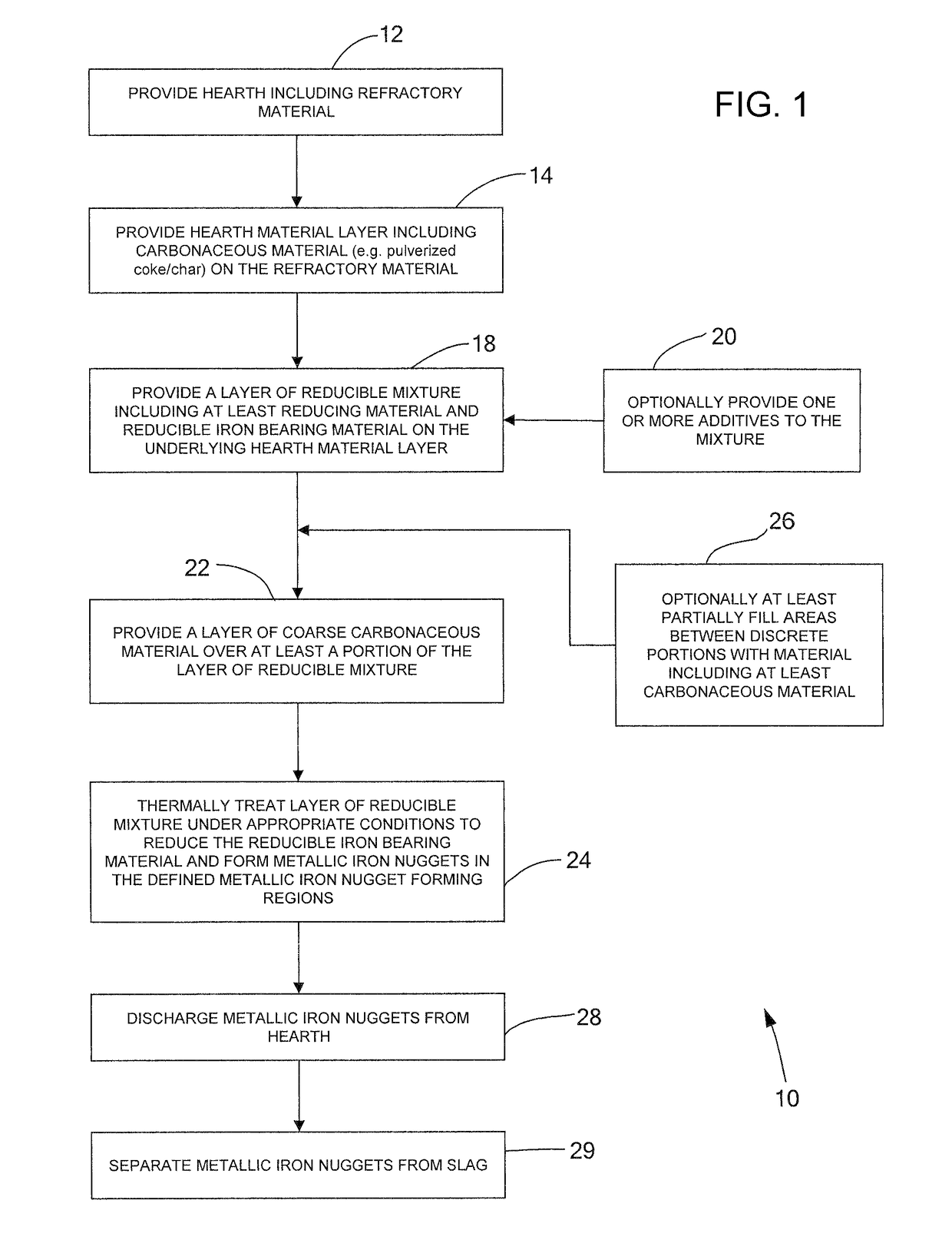
[0060]Certain embodiments of a process for the production of metallic iron nuggets are described with reference to FIGS. 1-3. Various other embodiments of the process for the production of metallic iron nuggets and examples supporting such various embodiments are also described with reference to the other Figures as described below. The method and system for producing metallic iron nuggets as will be described in further detail by way of example, together with one or more of the resulting benefits and features. As explained in detail hereinafter, the disclosed process permits the control of the amount of sulfur to produce a novel intermediate slag / metallic nugget product, and with separation, novel metallic iron nuggets.

[0061]FIG. 1 shows a block diagram of one or more generalized illustrative embodiments of a metallic iron nugget process 10. The metallic iron nugget process 10 shown in the block diagram shall be described with further reference to a more detailed embodiment shown i...


PUM

PropertyMeasurementUnit
temperatureaaaaaaaaaa

Abstract

Method and system for producing metallic nuggets includes providing reducible mixture of reducing material (such as carbonaceous material) and reducible iron bearing material (such as iron oxide) that may be arranged in discrete portions, such as mounds or briquettes, on at least a portion of a hearth material layer (such as carbonaceous material). A coarse overlayer of carbonaceous material may be provided over at least some of the discrete portions. Heating the reducible mixture to 1425° C. or 1400° C. or 1375° C. results in formation of an intermediate product of one or more metallic iron nuggets, which may have a sulfur content of less than 0.03%, and slag, which may have less than 5% mass MgO, which may have a ratio of percent by weight sulfur in the slag over percent by weight sulfur in the metallic nuggets of at least about 12 or at least about 15.

Description

CROSS-REFERENCE TO RELATED APPLICATIONS[0001]This application is a continuation of International Application No. PCT / US2007 / 074471, filed Jul. 26, 2007, which claims priority from U.S. Provisional Patent Application No. 60 / 820,366, filed Jul. 26, 2006. The disclosures of which are both incorporated herein by reference.[0002]This application is also a continuation-in-part of U.S. patent application Ser. No. 11 / 296,198, filed Dec. 7, 2005, updated as U.S. Pat. No. 7,695,544 B2, which claims priority from U.S. Provisional Patent Application No. 60 / 633,886, filed Dec. 7, 2004. The disclosures of which are both incorporated herein by reference.GOVERNMENT INTERESTS[0003]The present invention was made with support by the Economic Development Administration, Grant No. 06-69-04501, and the Department of Energy, Sponsor Award DE-FG36-05GO15185. The United States government may have certain rights in the invention.BACKGROUND AND SUMMARY[0004]The present invention relates to the reduction iron ...

Claims


Application Information

Patent Timeline
Patent Type & Authority Patents(United States)
IPC IPC(8): C21B13/10C22C38/00
CPCC21B13/0046C21B13/006C21B13/008C21B13/105C22B1/245C22B5/10F27B9/028F27B9/045F27B9/12F27B9/20F27B9/40
Inventor IWASAKI, IWAOLINDGREN, ANDREW J.KIESEL, RICHARD F.
Owner NU IRON TECH LLC
Why Eureka
Try Eureka