Method and apparatus for automated application of hardfacing material to rolling cutters of hybrid-type earth boring drill bits, hybrid drill bits comprising such hardfaced steel-toothed cutting elements, and methods of use thereof

a technology of hardfacing and cutting elements, which is applied in the field of automated or “robotic” application of hardfacing to the surface of a steeltoothed cutter of a rock bit, which can solve the problems of reducing the penetration rate of the drill bit, reducing the reliability of the final product, and increasing the consistency and quality of applied hardfacing. , the effect of reducing manufacturing costs

Inactive Publication Date: 2013-06-25
BAKER HUGHES HLDG LLC
View PDF218 Cites 18 Cited by
  • Summary
  • Abstract
  • Description
  • Claims
  • Application Information

AI Technical Summary

Benefits of technology

[0028]The primary advantage of the present invention is that it provides a system and method for automating the hardfacing application of rolling cutters, which increases the consistency and quality of the applied hardfacing, and thus the reliability, performance, and cost efficiency of the final product. Another advantage of the present invention is that it reduces manufacturing cost and reliance on skilled laborers. Another advantage of the present invention is that by decreasing production time, product inventory levels can be reduced. Another advantage of the present invention is that it facilitates the automated collection of welding data, from which further process controls and process design improvements can be made.
[0029]Another advantage of the present invention is that utilization of the robotic arm to manipulate the rolling cutter improves the opportunity to integrate sensors for providing feedback. Another advantage of the present invention is that utilization of the robotic arm to manipulate the rolling cutter provides the necessary surface-to-torch angularity for access, without disrupting the flow of the powder due to changes in the angle of the torch.
[0030]These aspects of the invention are not meant to be exclusive and other features, aspects, and other advantages of the present invention will be readily apparent to those of ordinary skill in the art when read in conjunction with the appended claims and accompanying drawings.
[0031]As referred to hereinabove, the “present invention” refers to one or more embodiments of the present invention, which may or may not be claimed, and such references are not intended to limit the language of the claims, or to be used to construe the claims in a limiting manner.

Problems solved by technology

As the rolling cutter cutters roll on the bottom of the hole being drilled, the teeth or carbide inserts apply a high compressive load to the rock and fracture it.
Under normal drilling conditions, the teeth of the steel-tooth bits are subject to continuous impact and abrasive wear because of their engagement with the rock being drilled.
As the teeth are worn away, the penetration rate of the drill bit is reduced, and the cost of drilling increases significantly.
Limited availability of qualified welders has aggravated the problem.
The manual application is extremely tedious, repetitive, skill-dependent, time-consuming, and expensive.
Indeed, application of cutter hardfacing is considered the single most tedious and skill-dependent step in the manufacture of a steel-toothed rock bit.
However, U.S. Pat. No. 6,392,190 fails to provide any specific teaching directed to the critical details of the numerous obstacles that must be overcome to actually reduce to practice the science of robotically automating the hardfacing of rolling cutters.
Indeed, to date, it is not known to have successfully automated the production of the application of hardfacing to rolling cutters.
One factor preventing commercial use of robotic hardfacing has been the unsatisfactory appearance of the final product when applied using robotically held torches over stationary cutters.
Another factor preventing commercial use of robotic hardfacing to rolling cutters is the commercial unavailability of a material that directly compares to conventional Oxygen Acetylene Welding (OAW) welding rod materials that can be applied with commercially available Plasma Transferred Arc (PTA) torches.
Another factor preventing commercial use of robotic hardfacing is the inability to properly identify and locate individual rolling cutter designs within a robotic hardfacing system.
The cutters of each bit size and style are different, and initiating the wrong program could cause a collision of the torch and part, resulting in catastrophic failure and loss.
Another factor preventing commercial use of robotic hardfacing is the inability to correct the critical positioning between the torch and part in response to manufacturing variations of the cutter, wear of the torch, and buildup of hardfacing.
Still another factor preventing commercial use of robotic hardfacing has been the inability to properly access many of the areas on the complex surface of a rolling cutter that require hardfacing with commercially available Plasma Transferred Arc (PTA) torches large enough to permit application of the required material.
Torches with smaller nozzles have smaller powder ports that prohibit proper flow of the desired powders.
Another factor preventing commercial use of robotic hardfacing is the complexity of programming the control system to coordinate the critical paths and applications sequences needed to apply the hardfacing.
A related factor preventing commercial use of robotic hardfacing is the cost and limitation of resources.

Method used


Image

  • Method and apparatus for automated application of hardfacing material to rolling cutters of hybrid-type earth boring drill bits, hybrid drill bits comprising such hardfaced steel-toothed cutting elements, and methods of use thereof
  • Method and apparatus for automated application of hardfacing material to rolling cutters of hybrid-type earth boring drill bits, hybrid drill bits comprising such hardfaced steel-toothed cutting elements, and methods of use thereof
  • Method and apparatus for automated application of hardfacing material to rolling cutters of hybrid-type earth boring drill bits, hybrid drill bits comprising such hardfaced steel-toothed cutting elements, and methods of use thereof

Examples


Embodiment Construction

[0062]The following description is presented to enable any person skilled in the art to make and use the invention, and is provided in the context of a particular application and its requirements. Various modifications to the disclosed embodiments will be readily apparent to those skilled in the art, and the general principles defined herein may be applied to other embodiments and applications without departing from the spirit and scope of the present invention. Thus, the present invention is not intended to be limited to the embodiments shown, but is to be accorded the widest scope consistent with the principles and features disclosed herein.

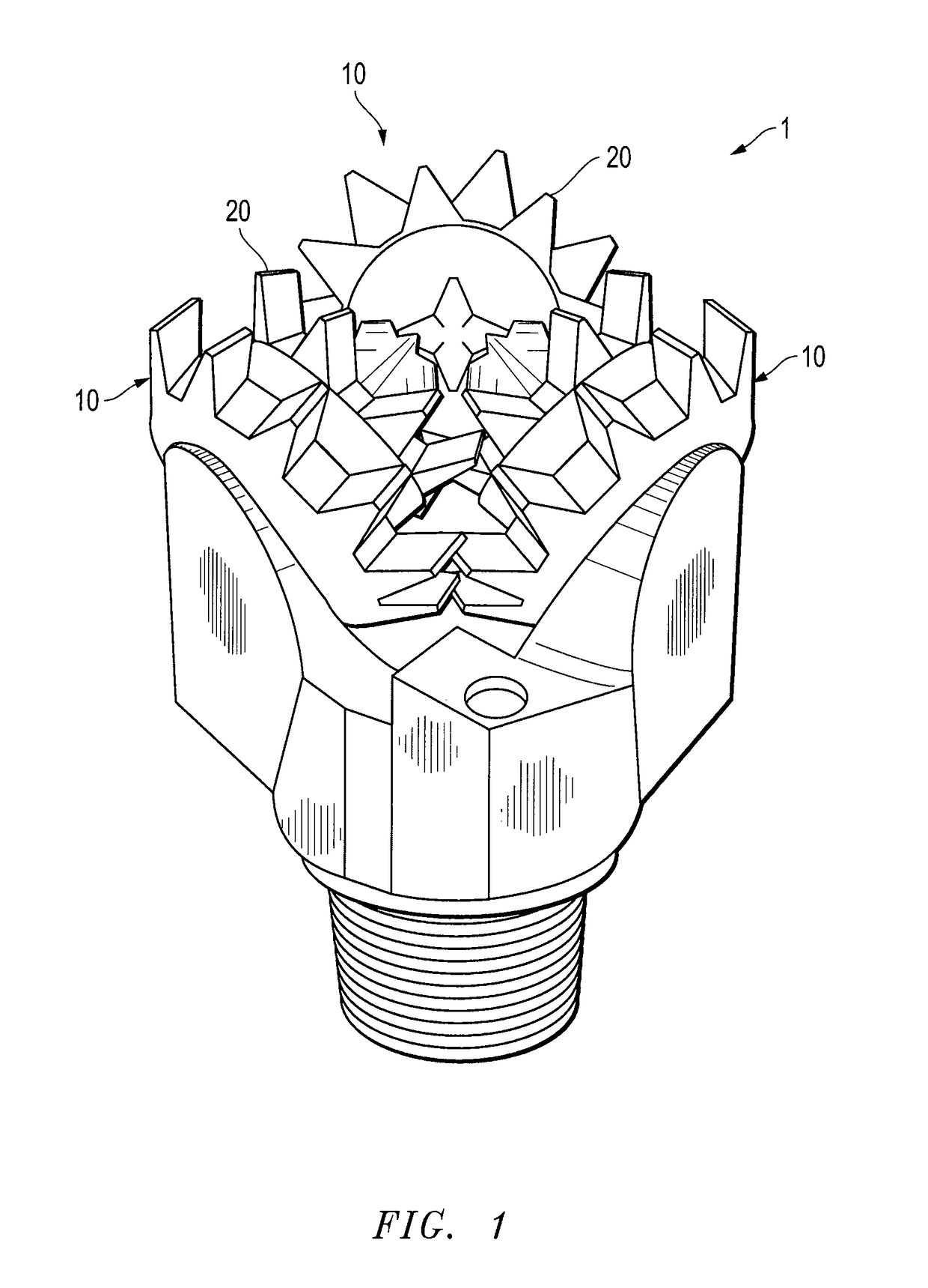
[0063]FIG. 1 is a side view of an exemplary steel-tooth drill bit 1 in accordance with the present disclosure. While the bit 1 illustrated therein is of the typical roller-cone or ‘tricone’ type, the phrase “steel-tooth drill bit” as used herein is meant to include the roller cones of hybrid-type earth boring drill bits, as will be described in...


PUM

PropertyMeasurementUnit
diameteraaaaaaaaaa
path lengthaaaaaaaaaa

Abstract

The present invention relates to a system and method for automated or “robotic” application of hardfacing to the surface of a steel-toothed cutter of a standard earth-boring rock bit or a hybrid-type rock bit. In particular, the system incorporates a grounded adapter plate and chuck mounted to a robotic arm for grasping and manipulating a rock bit cutter, particularly a hybrid rock bit cutter, beneath an electrical or photonic energy welding source, such as a plasma arc welding torch manipulated by a positioner. In this configuration, the torch is positioned substantially vertically and oscillated along a horizontal axis as the cutter is manipulated relative along a target path for the distribution of hardfacing. Moving the cutter beneath the torch allows more areas of more teeth to be overlayed, and allows superior placement for operational feedback, such as automatic positioning and parameter correction. In the preferred embodiment, sensors provide data to the control system for identification, positioning, welding program selection, and welding program correction. The control system, aided by data from the sensors, manipulates the robotically held cutter while controlling the operation and oscillation of the torch. These systems and methods can be applied to hardfacing steel teeth of the rolling cutters of both standard tri-cone or di-cone type rolling cone bits, as well as to hybrid-type earth boring drill bits.

Description

CROSS-REFERENCE TO RELATED APPLICATIONS[0001]The present application claims priority to U.S. Provisional Patent Application Ser. No. 61 / 141,668, filed Dec. 31, 2008, the contents of all of which are incorporated herein by reference.STATEMENT REGARDING FEDERALLY-SPONSORED RESEARCH OR DEVELOPMENT[0002]Not applicable.REFERENCE TO APPENDIX[0003]Not applicable.TECHNICAL FIELD OF THE INVENTION[0004]The present invention relates to a system and method for automated or “robotic” application of hardfacing to the surface of a steel-toothed cutter of a rock bit, particularly a hybrid-type earth boring rock bit. In particular, the system incorporates an adapter plate and chuck mounted to a robotic arm for manipulating a rock bit cutter under a plasma arc welding torch manipulated by a positioner. Sensors provide data to the control system for identification, positioning, welding program selection, and welding program correction. The control system, aided by data from the sensors, manipulates th...

Claims


Application Information

Patent Timeline
Patent Type & Authority Patents(United States)
IPC IPC(8): B23K13/01
CPCB23K9/044B23K10/027H05H1/3405H05H1/42H05H2001/3421H05H2001/3426H05H2001/3457H05H1/3421H05H1/3457
Inventor STAUFFER, BRUCELUCE, DAVIDMASSEY, ALANGILMORE, KENNETHNEHRING, KEITH
Owner BAKER HUGHES HLDG LLC
Why Eureka
Try Eureka