Resonant circuits

a technology of resonance circuit and circuit, applied in the direction of generator stabilization, pulse manipulation, pulse generator, etc., can solve the problems of limiting the operation range, limiting the read range, and limiting the energy transfer efficiency between the two circuits, so as to reduce the effect of chirp decay, and reduce the effect of chirp

Active Publication Date: 2013-06-25
SUREFLAP
View PDF12 Cites 22 Cited by
  • Summary
  • Abstract
  • Description
  • Claims
  • Application Information

AI Technical Summary

Benefits of technology

[0019]In embodiments the duty cycle is set by a switching element, more particularly a FET with a source potential that varies with the resonance amplitude. The charge required to turn the FET on or off is supplied by the resonance current in the inductor; it is therefore efficient and does not require an external power source; as such the method may have application both in a reader and also a transponder. If implemented in a transponder then the transponder will be responsive to a range of energising frequencies, potentially allowing operation across locations with different regulatory frequencies.
[0021]In high coupling situations a transponder may include a regulator to limit the pickup voltage and avoid damage to the rest of the circuitry. However such a transponder can pickup a significant proportion of the energising field, which is subsequently dissipated as heat in the regulator. Embodiments of the transponder we describe limit the pickup voltage through the relative phase between the pickup voltage and the energising field. The level of pickup is limited in the high coupling case, which can avoid issues with the transponder shading the energising field. This can be beneficial when reading multiple transponders.
[0035]Broadly speaking embodiments of the circuit are useful where very efficient coupling over a relatively wide range of frequencies is desirable. Embodiments of the circuit facilitate coupling between two high Q systems without the need for very precise alignment of the resonant peaks which would otherwise be necessary. This facilitates, for example, highly efficient inductive charging. Embodiments of the technique also facilitate the efficient operation of an rf tag over a plurality of frequencies or bands of operation, for example facilitating the provision of a single tag capable of operating in accordance with different US and European prescribed frequency standards (for example over the range 125 KHz to 134 KHz).
[0043]Embodiments employ a decaying chirp waveform that links the amplitude of the chirp to the frequency of the chirp. This waveform allows a more sensitive measurement of energy loss through the phase of the decaying waveform. Small changes in the energy absorbed from the antenna cause corresponding changes to the frequency of the decay, in addition to the amplitude. Comparing two levels of damping, once the two chirps are operating at different frequencies their phase difference increases with time. Consequently, after a delay of many cycles the small difference in damping between the two waveforms may be picked up by a straightforward sampling of the chirp waveform. The phase difference between the two waveforms, once it amounts to a significant fraction of a cycle, translates to a large fractional change in the sampled voltage. This is in contrast to an amplitude measurement, which would display a much smaller effect. Registering changes in damping through the phase of the chirp decay can potentially offer improved sensitivity.
[0044]The frequency sweep of the chirp decay may be used to determine the transponder resonant frequency. As the frequency sweeps over the transponder resonance, the effect of the transponder on the antenna is maximised. For the case where the chirp starts at low frequency and sweeps to a higher frequency then the effect of increasing the transponder resonant frequency is to delay the corresponding change to the chirp. Rather than sampling the chirp at one point only, sampling at a number of points along the length of the decay therefore provides information relating to the transponder resonance frequency. This measurement may either be carried out every time the chirp is generated, or alternatively a change in the system may be registered from a single point measurement and subsequently the transponder frequency determined from a multi-point measurement of the chirp. Once the transponder resonant frequency has been determined the antenna may be tuned accordingly for the subsequent full power identification mode. This multi-point measurement may also beneficially discriminate between a transponder with a clear resonance and interfering objects that absorb energy over a wide frequency range, for example metallic objects.

Problems solved by technology

Their use increases the efficiency of energy transfer between the two circuits, which would otherwise be much lower, severely limiting the range of operation.
Such constraints may limit the Q of the two circuits to relatively low levels, which may in turn limit the read range and / or lead to excessive power requirements.
The tuning circuit can require many components, comprising the set of capacitors and the switches to couple them into the resonance; this adds to the system complexity and cost.
Such constraints can limit the feasible tuning accuracy and resolution.
If it is made real-time, such as the method described in U.S. Pat. No. 5,491,715, then this adds complexity and cost.
If significantly de-tuned, then the transponder would not be able to charge up enough to run a tuning circuit.
As such, the prior art tuning methods described are usually unsuitable for a passive transponder.
This fixed tuning step adds to the cost of manufacture and cannot adjust to environmental changes that might affect the transponder resonant frequency.
Prior art methods provide no facility for this.

Method used


Image

  • Resonant circuits
  • Resonant circuits
  • Resonant circuits

Examples


second embodiment

[0093]FIG. 5 shows an alternative embodiment of the invention. In addition to the n-type PET shown in FIG. 1, this embodiment also includes a p-type FET. The state of the n-type FET changes on the negative cycle of the FET drain, and the p-type FET changes on the positive cycle. For low amplitudes both FETs are non-conducting, whereas for high amplitudes both are conducting. The design equations for the frequency limits at 0% duty cycle and 100% duty cycle (duty cycle is the fraction of the cycle that at least one of the FETs is conducting) are as follows:

[0094]f100⁢%=1π⁡(L·(C⁢⁢1-C⁢⁢3)+L·(C⁢⁢1+C⁢⁢5))f0⁢%=1π⁡(L·(C⁢⁢1+(C⁢⁢2-1+C⁢⁢3-1)-1)+L·(C⁢⁢1+(C⁢⁢4-1+C⁢⁢5-1)-1))

[0095]The values shown in FIG. 5 give a frequency range of f100%=104 kHz and f0%=147 kHz. When setting the amplitude of the resonance with the gate voltages Vgate1, 15, and Vgate2, 16, this is done in a similar manner to the single FET version of the first embodiment except that these voltages should go in opposite directions...

third embodiment

[0097]FIG. 6 shows an embodiment of a circuit which can be used to extract power from an rf field, for example for an RFID transponder, or other remotely powered device. This circuit is driven by an rf field in which it is located. Power can be taken from the circuit at any convenient point, for example across C1 and rectified. To provide a return signal from the transponder power from the circuit may, for example, be used to power an rf oscillator which can be modulated with the return signal. The transponder inductance is increased relative to the earlier 300 μH transmitting antenna example (FIG. 1). This is to increase the induced voltage in the transponder in response to an oscillating field. The capacitors C1, C2, C3 are reduced by the same factor resulting in the same frequency range as the first embodiment (f50%=106 kHz, f0%=145 kHz). The Q of the transponder is set by the coil effective series resistance (R1), which has been set to 10Ω in this example, giving a high Q of app...

fourth embodiment

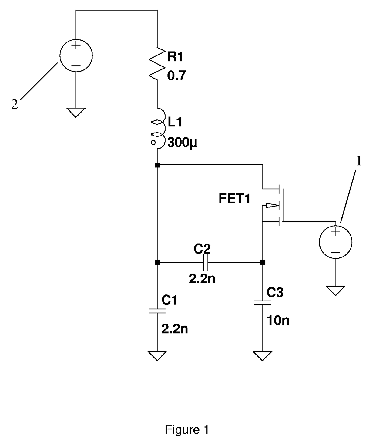
[0111]In a fourth embodiment, the circuit shown in FIG. 1 is used in free decay, rather than steady state excitation. When used in free decay, the duty cycle of FET conduction is determined by the decay waveform, and changes as a function of time. The resultant behaviour is a chirp signal, rising in frequency as the energy in the circuit decays. This embodiment may be used in a reader to detect the presence of a transponder and / or its resonant frequency.

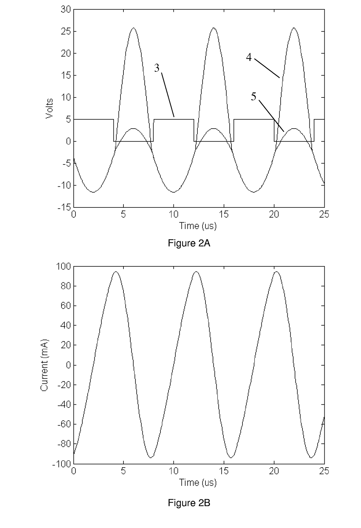
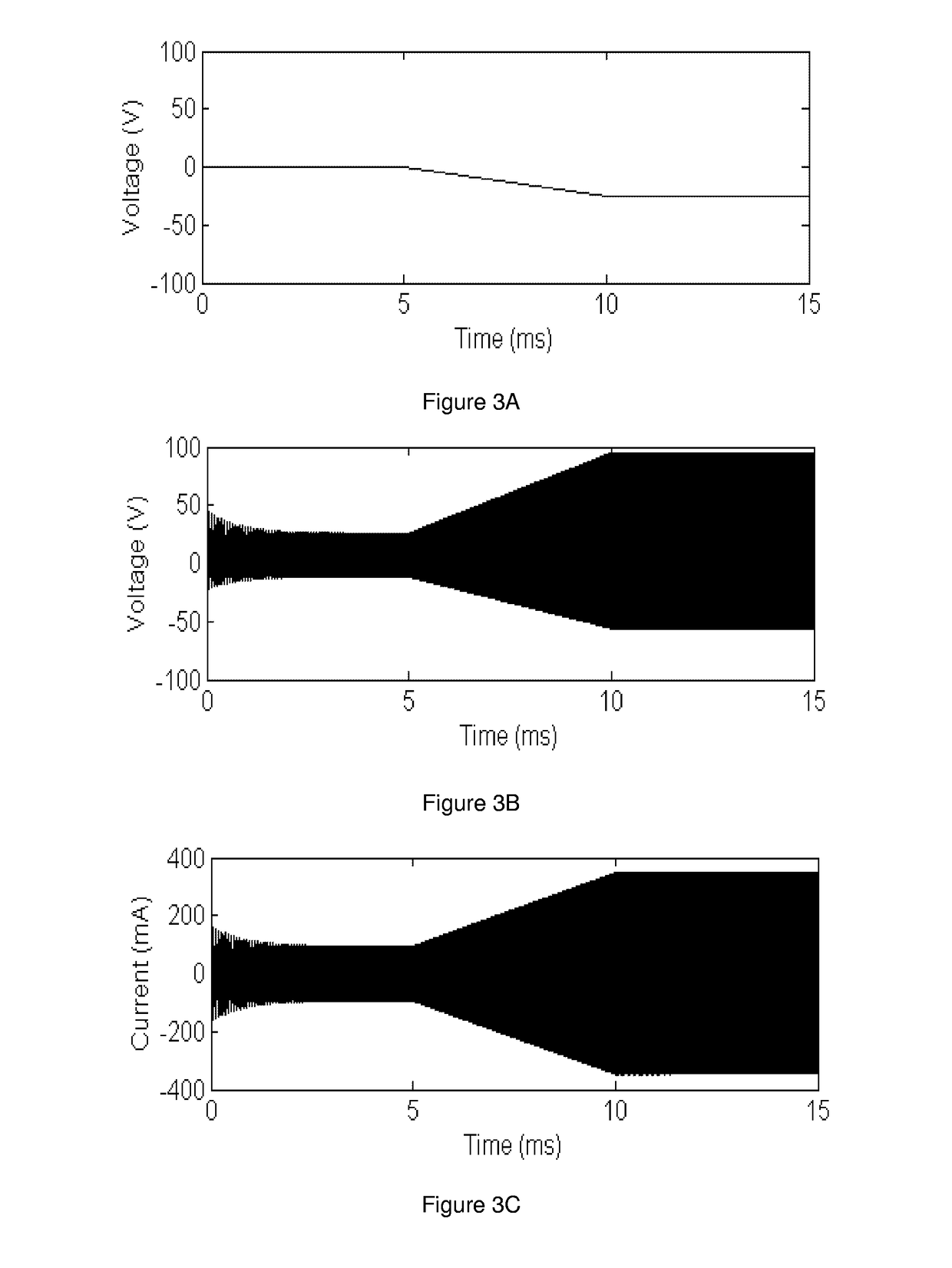
[0112]A 4 μs square voltage pulse of amplitude 5V is applied to Vstimulus, 2, and the FET gate voltage, 1, is kept at 0V. FIG. 10A shows the decay of the FET drain voltage and FIG. 10B shows the antenna current. The drain voltage is asymmetric when the FET duty cycle is non-zero, which is a natural consequence of the two different capacitances coupled into the resonance. The antenna current on the other hand is more symmetric.

[0113]FIG. 10C shows the instantaneous frequency of the chirp as a function of time. The chirp starts off at ...


PUM


Abstract

Embodiments of the invention relate to resonant circuits; particularly but not exclusively the embodiments relate to resonant circuits in RPID (radio frequency identification) responsive to a wide frequency range. A controllable electric resonator comprising an inductor coupled to a first capacitor to form a resonant circuit, the resonator further comprising a controllable element, a second capacitor controllable coupled across said first capacitor by said controllable element, and a control device to control said controllable element such that a total effective capacitance of said first and second capacitor varies over a duty cycle of an oscillatory signal on said resonator.

Description

FIELD OF INVENTION[0001]Broadly, the invention relates to resonant circuits. Embodiments of the invention relate particularly but not exclusively to resonant circuits in RFID (radio frequency identification) responsive to a wide frequency range. Embodiments of the invention also relate to low power proximity detection of an RFID (radio frequency identification) transponder.BACKGROUND TO THE INVENTION[0002]In an RFID system resonant circuits are generally used in both the reader and the transponder. Their use increases the efficiency of energy transfer between the two circuits, which would otherwise be much lower, severely limiting the range of operation. Optimal read range may be achieved when the reader is stimulated at its resonance frequency, and this also matches the resonant frequency of the transponder. The task of operating both these units at their resonant frequencies is complicated by the following factors:[0003]1) The LC manufactured components have tolerances on their va...

Claims


Application Information

Patent Timeline
Patent Type & Authority Patents(United States)
IPC IPC(8): H03K3/282
CPCH03J1/0008G06K19/0723
Inventor HILL, NICHOLAS PATRICK ROLAND
Owner SUREFLAP
Why Eureka
Try Eureka