Heating device and method

a heat transfer device and heat transfer technology, applied in the field of thermodynamics, can solve the problems of poor heat transfer, increased difficulty in obtaining firewood, and diminishing availability and ease of obtaining firewood, and achieve the effect of high-efficiency fuel combustion

Active Publication Date: 2013-07-09
FIGUEROA OSCAR ENRIQUE
View PDF149 Cites 9 Cited by
  • Summary
  • Abstract
  • Description
  • Claims
  • Application Information

AI Technical Summary

Benefits of technology

[0007]One feature of the present invention is a new and useful heating device, that is particularly characterized by the efficient way it provides combustion of a carbon based fuel (e.g. wood). A vertically oriented combustion chamber is configured with a relatively narrow, lower portion, a relatively wider upper portion, and a vertically oriented wall structure defining the combustion chamber. The vertically oriented wall structure has a plurality of inlet openings to enable air to enter the combustion chamber. A source of air is in fluid communication with the wall structure of the combustion chamber, and a fluid conduit system is configured to direct air from the source along a predetermined path about the vertically oriented wall structure of the combustion chamber. The combustion chamber has support structure configured to (i) support a mass of a carbon based fuel in the relatively narrow, lower portion of the combustion chamber, above the bottom of the combustion chamber and away from the air inlet openings in the vertically oriented wall structure, and (ii) enable air flowing along the predetermined path about the vertically oriented wall structure to flow into the combustion chamber through the inlet openings; whereby the air entering the combustion chamber can substantially envelop and support combustion of the mass of carbon based fuel located in the combustion chamber. The relatively narrow and wider portions of the combustion chamber are configured to allow gases generated from combustion of a carbon based fuel in the relatively narrow portion of the combustion chamber to expand as they rise into the relatively wider portion of the combustion chamber, in a manner that reduces the output speed of the gases, increases the residence time of the gases in the combustion chamber, thereby to improve the efficiency with which heat is generated in the combustion chamber from a carbon based fuel.
[0009]The configuration of the combustion chamber, the air entering the combustion chamber through the first and second arrays of air inlet openings, and the air turbulence promote substantially complete combustion of the volatile organic compounds of the carbon based fuel.
[0013]Still further, according to a preferred embodiment, the support structure for the mass of carbon based fuel comprises a basket like structure comprising a plurality of ribs disposed inside the combustion chamber, the ribs located and configured to support a mass of carbon based fuel above the bottom of the combustions chamber and away from the vertically oriented wall structure. Also, the heating plate structure and the heating chamber are configured such that heat and / or heated air from the heating chamber will sweep along the heating plate structure in a predetermined direction as heat is being transferred to the heating plate structure. In addition, the heating chamber can be used to heat one or a plurality of pieces of cookware in heat transfer relationship with respective portions of the heating chamber. Moreover, a layer of insulation surrounds the walls of the heating chamber, to minimize transfer of heat from the walls of the heating chamber to the environment outside the heating chamber.
[0014]In a cooking method according to the principles of the present invention, a vertically oriented, combustion chamber is provided with a vertically oriented wall structure having a relatively narrow, lower portion, and a relatively wider upper portion, and air inlet openings located in the vertically oriented wall structure to enable air to be directed into the combustion chamber. Moreover, a heating chamber is provided above and in heat transfer relationship with the relatively wider upper portion of the combustion chamber and heating plate structure is in direct heat transfer relation with the heating chamber. A mass of carbon based fuel is located in the relatively narrow lower portion of the combustion chamber, above the bottom of the lower portion of the combustion chamber, and spaced from the air inlet openings in the vertically oriented wall structure of the combustion chamber. Air is directed along a predetermined path that enables the air to enter the combustion chamber through the air inlet openings in the vertically oriented wall structure, in a manner that supports substantially complete combustion of the carbon based fuel in the combustion chamber, and generation of heat from the combustion of the carbon based fuel; and substantially all of the heat generated from combustion of the carbon based fuel in the combustion chamber is directed into the heating chamber, so that substantially all of the heat from the combustion chamber is transferred to the heating plate structure.
[0015]According to a preferred method, air is directed along a path that enables air to flow into the combustion chamber comprises directing air along a path that enables air to flow into the combustion chamber in directions lateral to the mass of carbon based fuel located in the combustion chamber, and in a manner that enables at least some air to flow into the area below the mass of carbon based fuel and at least some of the air to flow into the combustion chamber above the mass of carbon based fuel, further to enhance the efficiency with which heat is generated from the carbon based fuel in the combustion chamber. Also, the air is directed along a path that enables at least some air to flow into the combustion chamber above the mass of carbon based fuel located in the narrow portion of the combustion chamber to create air turbulence above the mass of carbon based fuel located in the combustion chamber. The air that is directed along the predetermined path is swept along the exterior of the combustion chamber, in a substantially spiral path, so that heat from the exterior of the combustion chamber is transferred to the air that is being swept along the exterior of the combustion chamber.
[0018]With the device and method of the present invention, highly efficient firewood combustion is provided, and the heated gases from combustions are used in a highly efficient way to heat food. The incandescent gases generated from combustion undergo a process of expansion because they travel from a smaller diameter to a larger diameter, achieving a reduction in the output speed and increasing the time of residence within the combustion chamber; and this momentary retention of gases within the combustion chamber achieves a highly efficient combustion. The heat generated by the combustion chamber is transferred to a heating chamber and used in a way that provides an efficient heating process, particularly for heating food product. The heat generating / transferring device of the invention is mounted on a worktable that facilitates the preparation and cooking of food. The worktable also provides enough space to store firewood, cookware and at the same time allows space for several (e.g. three) people to sit around it to eat.

Problems solved by technology

Cooking, an everyday chore, not only transfers heat poorly but, has consequences in human health and in the environment due to the gases generated by the inefficiency of the many firewood combustion methods.
However, the availability and ease of obtaining firewood seems to be diminishing due to scarcity of available wood.
Intensive logging, deforestation for agriculture, grazing land for cattle and inefficient burning methods are causing an increased difficulty in obtaining firewood.
The same firewood that has increased human survival by making food preparation easy has also been the cause of respiratory illnesses and other health problems.
Traditional combustion is often inefficient, incomplete and generates gases which can cause various health problems.
In recent years, many private, social, governmental and other entities have made efforts to design and disseminate new methods and devices for more efficient combustion of fuel in order to solve the problem, but in applicant's experience these efforts do not appear to have had provided a real, effective solution.

Method used


Image

  • Heating device and method
  • Heating device and method
  • Heating device and method

Examples


Embodiment Construction

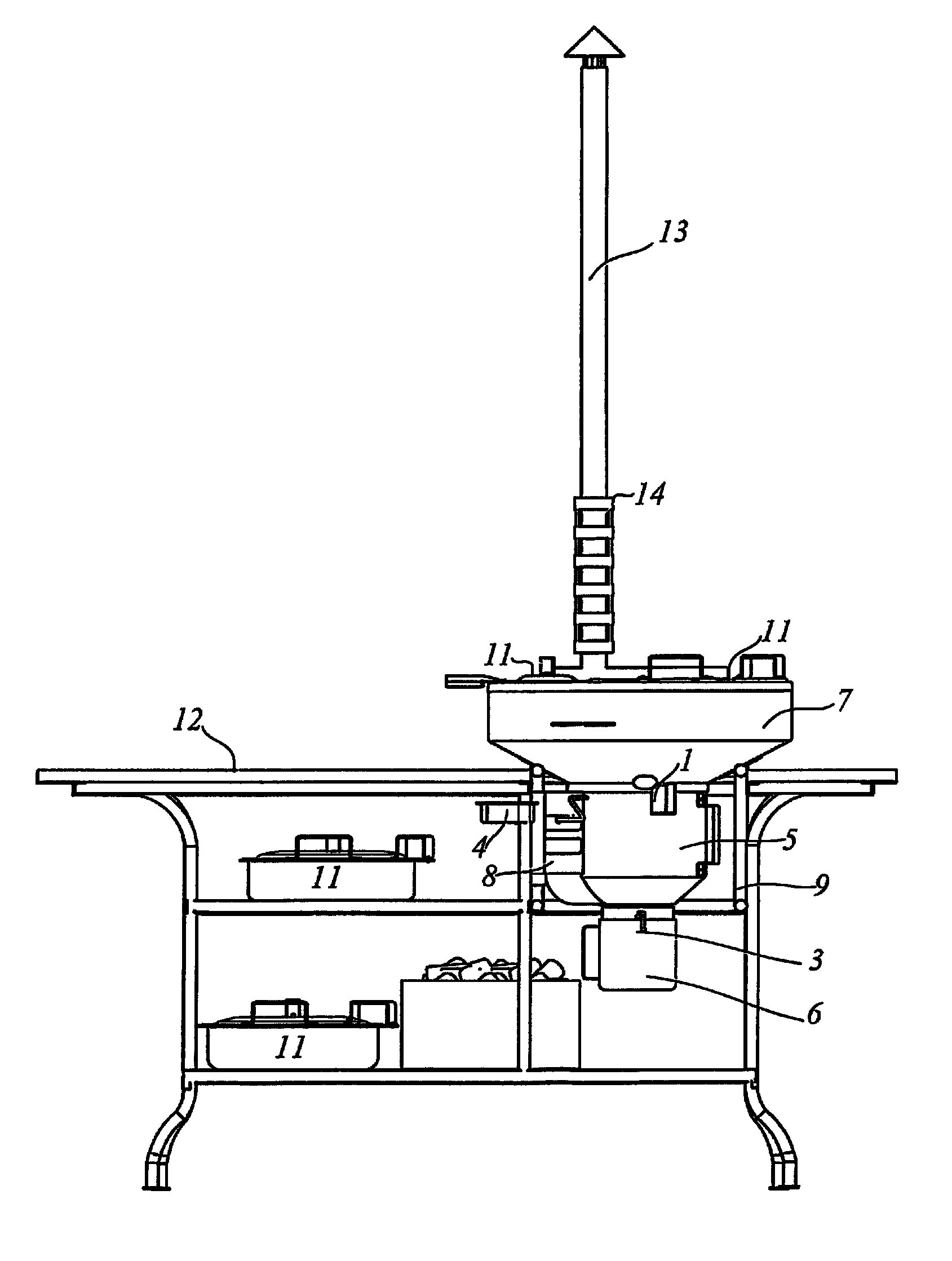
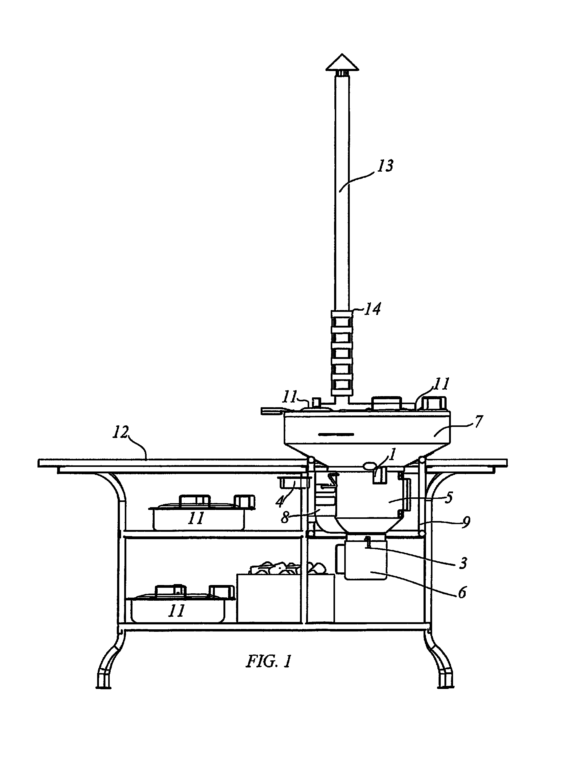
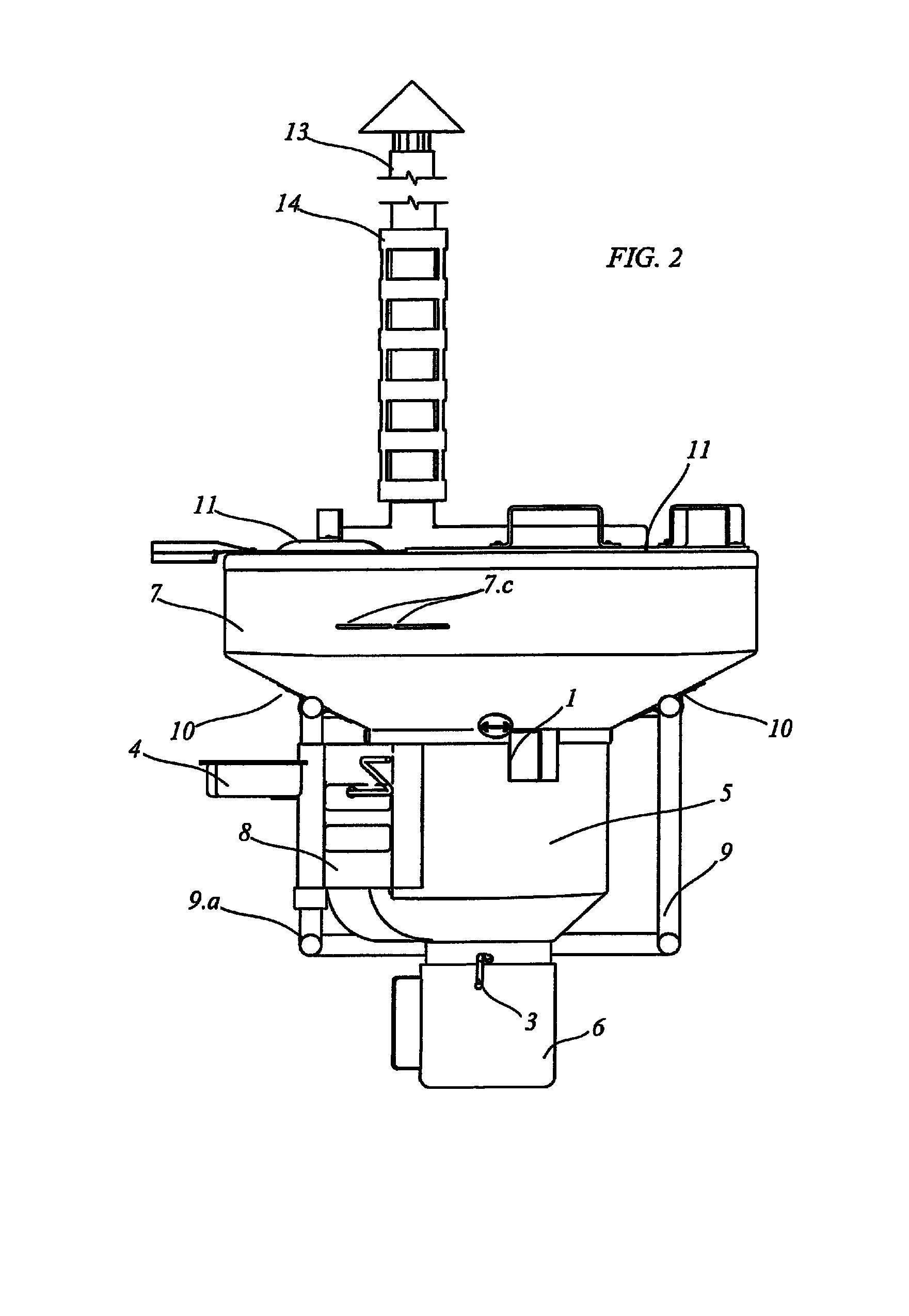
[0037]As described above, the present invention provides a heat generating / transferring device and method, that is particularly useful in heating food products. The principles of the present invention are described below in connection with a system and method for heating food products, and from that description the manner in which the principles of the invention can be used for various types of heating applications will be apparent to those in the art.

[0038]One feature of the present invention is a new and useful heating device, that is particularly characterized by the efficient way it provides combustion of a carbon based fuel (e.g. wood). A vertically oriented combustion chamber 1 is configured with a relatively narrow, lower portion, a relatively wider upper portion, and a vertically oriented wall structure 1.j (see e.g. FIGS. 8A, 9A, 9C, 10) defining the combustion chamber. The vertically oriented wall structure has arrays of inlet openings 1.b, 1.c, to enable air to enter the ...


PUM


Abstract

A new and useful heating device is provided, that is particularly characterized by the efficient way it provides combustion of a carbon based fuel (e.g. wood). A vertically oriented combustion chamber is configured with a relatively narrow, lower portion, a relatively wider upper portion, and a vertically oriented wall structure defining the combustion chamber.

Description

BACKGROUND[0001]The present invention relates to the field of thermodynamics, particularly in the generation and transfer of heat, and has its specific application in the burning of firewood for cooking for residential use.[0002]Many households in developing and impoverished countries around the world depend heavily on firewood for cooking. Cooking, an everyday chore, not only transfers heat poorly but, has consequences in human health and in the environment due to the gases generated by the inefficiency of the many firewood combustion methods.[0003]From ancient times to the present day, fire has been a valuable tool for human beings; until now, the abundance and availability of firewood has solved heating and cooking needs with ease. However, the availability and ease of obtaining firewood seems to be diminishing due to scarcity of available wood. Intensive logging, deforestation for agriculture, grazing land for cattle and inefficient burning methods are causing an increased diffi...

Claims


Application Information

Patent Timeline
Patent Type & Authority Patents(United States)
IPC IPC(8): A01H5/08
CPCA47J37/0704
Inventor FIGUEROA, OSCAR ENRIQUE
Owner FIGUEROA OSCAR ENRIQUE
Why Eureka
Try Eureka