Front accessible switchgear assembly

a switchgear and front access technology, applied in the field of front access switchgear assembly, electrical enclosure, can solve the problems of large space occupied by the switchgear cabinet for medium voltage equipment, inefficient use of valuable floor space, and inability to meet the needs of adjacent equipment and structures,

Active Publication Date: 2013-07-09
IEM HLDG GRP INC
View PDF11 Cites 16 Cited by
  • Summary
  • Abstract
  • Description
  • Claims
  • Application Information

AI Technical Summary

Benefits of technology

[0013]The front accessible metal clad switchgear assembly disclosed herein addresses the above stated need for a compact arc resistant front accessible metal clad switchgear assembly that has a compact footprint and provides front access to electrical components and equipment accommodated in the switchgear assembly for inspection, testing and maintenance with limited space requirements and without protective gear. Adjacent sections defined in an electrical enclosure of the front accessible metal clad switchgear assembly are separated by vertical metal barriers for compartmentalizing active electrical components in the electrical enclosure. The “front accessible metal clad switchgear assembly” is herein referred to as a “front accessible switchgear assembly”. The front accessible switchgear assembly disclosed herein allows successful testing of the electrical components, for example, circuit breakers, that are accommodated in the front accessible switchgear assembly without additional heat sinks.
[0015]The front accessible switchgear assembly disclosed herein further comprises a plenum chamber rearwardly positioned in the electrical enclosure. The plenum chamber is in communication with one or more of the compartments within the electrical enclosure, for example, via an exhaust chamber. The exhaust chamber is in adjacent communication with the plenum chamber. The plenum chamber provides an exit path for releasing pressure and gases generated by the electrical components accommodated in the compartments during an event of arcing within the electrical enclosure. The front accessible switchgear assembly disclosed herein further comprises flaps positioned between the compartments and the plenum chamber for preventing the gases and external particulate matter from escaping the plenum chamber and entering into the compartments via the plenum chamber. One of the compartments, for example, an upper compartment, is configured as a low voltage compartment for accommodating control equipment. In an embodiment, the low voltage compartment is isolated from the plenum chamber and other compartments, for example, the high voltage compartments in the front accessible switchgear assembly.
[0016]The mounting block assembly is positioned in one or more of the compartments for mounting one or more of the electrical components and for providing front access to the mounted electrical components for inspection and maintenance. Each mounting block assembly comprises a base mounting block, multiple mounting legs, and a mounting block cover. The mounting legs extend frontwardly from the base mounting block for mounting the electrical components and allowing front access to the mounted electrical components. The mounting block cover is removably attached to the base mounting block for enclosing the mounted electrical components on the mounting legs. The mounting block cover is removable for providing front access to the mounted electrical components for inspection and maintenance. The mounting block assembly is configured to reduce temperature rise in the compartments.
[0018]The front accessible switchgear assembly disclosed herein further comprises one or more fuse sleeve assemblies operably connected to the control power transformer and the epoxy encapsulated potential transformer. The fuse sleeve assemblies allow high voltage primary connections of the control power transformer and the epoxy encapsulated potential transformer in the electrical enclosure. The fuse sleeve assemblies operably connected to the control power transformer and the epoxy encapsulated potential transformer contact one or more of the bus bars in, for example, a rear compartment within the electrical enclosure via the mounting block assembly, thereby creating an ultra compact front accessible switchgear assembly. The fuse sleeve assemblies contact a cylindrical bus mounted in the mounting block assembly. The mounting block assembly is configured to accommodate each of the fuse sleeve assemblies and isolate phases of the control power transformer and the epoxy encapsulated potential transformer. The control power transformer and the epoxy encapsulated potential transformer comprise low voltage contacts configured to disengage from low voltage connections within the electrical enclosure for preventing an event of arcing.
[0021]The front accessible switchgear assembly disclosed herein further comprises one or more infrared windows positioned at predetermined locations on a front side of the front accessible switchgear assembly for front scanning the electrical components and the bus bars in the compartments for inspection and maintenance. In an embodiment, support brackets are connected to the infrared windows for protecting the infrared windows from rupture. The front accessible switchgear assembly disclosed herein further comprises one or more inspection windows, for example, windows made of Lexan® of Saudi Basic Industries Corp, positioned at predetermined locations on the front side of the front accessible switchgear assembly for providing a front visual indication of the electrical components and the bus bars for inspection and maintenance and for critical electrical high voltage connections.
[0022]The front accessible switchgear assembly disclosed herein further comprises surge arresters positioned in the rear compartments within the electrical enclosure. The surge arresters protect the electrical components, the bus bars, the mounting block assembly, the inspection windows, the infrared windows, the input electrical cables, the output electrical cables, and the compartments defined with the electrical enclosure in an event of a lightning surge. The surge arresters are electrically connected to the bus bars in the electrical enclosure via short high voltage electrical cables. The surge arresters are compact and represent a unique way to mount and connect them to make the front accessible switchgear assembly compact.

Problems solved by technology

The switchgear cabinet for medium voltage equipment typically occupies a large space and is difficult to access.
Furthermore, a certain amount of space is required between adjacent equipment and structures such as walls and the switchgear cabinet per the national electric code (NEC) and other local codes.
Allocation of a substantial amount of space, for example, an entire room for the medium voltage switchgear cabinet is an undesirable and inefficient use of valuable floor space.
Switchgear cabinets, particularly medium voltage metal clad switchgear cabinets are often damaged due to arcing.
An explosion caused by arcing within a switchgear cabinet results in significant economic loss due to interruption of energy distribution, and damage of the switchgear cabinet and the components or equipment accommodated in the switchgear cabinet.
Consequently, maintenance personnel inspecting and servicing the switchgear cabinets have to wear protective gear that is bulky and expensive.
Such configurations require significant space.
However, these switchgear cabinets have cable connection bus bars in the rear making it difficult to install and service electrical components and the bus bars accommodated within these switchgear cabinets.
Furthermore, conventional switchgear cabinets utilize bar type current transformers that are mounted in the rear making it difficult to replace a transformer in the field if one of the transformers fail.
Moreover, there are significant limitations with respect to the size of potential transformers and control power transformers that are available in conventional switchgear cabinets.
These standards require a circuit breaker to be tested inside the switchgear cabinets that have limited cooling and therefore limiting the temperature rise within the switchgear cabinet becomes a major challenge.
Furthermore, conventional metal clad switchgear cabinets pose additional challenges to meet ANSI and Underwriters Laboratories (UL) requirements because of limited space and limited cooling.
In addition, IEEE / ANSI designed equipment requires bus bars within the switchgear cabinet to be insulated, making it more difficult to cool the critical current carrying bus bars in certain compartments of the switchgear cabinet that accommodate the circuit breaker.
Alternatively, expensive heat sinks have to be employed to limit temperature rise.
The addition of heat sinks is a difficult task in the compact space available and poses significant challenges to pass the required lightning impulse test due to space limitations and the shape of the heat sink.

Method used


Image

  • Front accessible switchgear assembly
  • Front accessible switchgear assembly
  • Front accessible switchgear assembly

Examples


Embodiment Construction

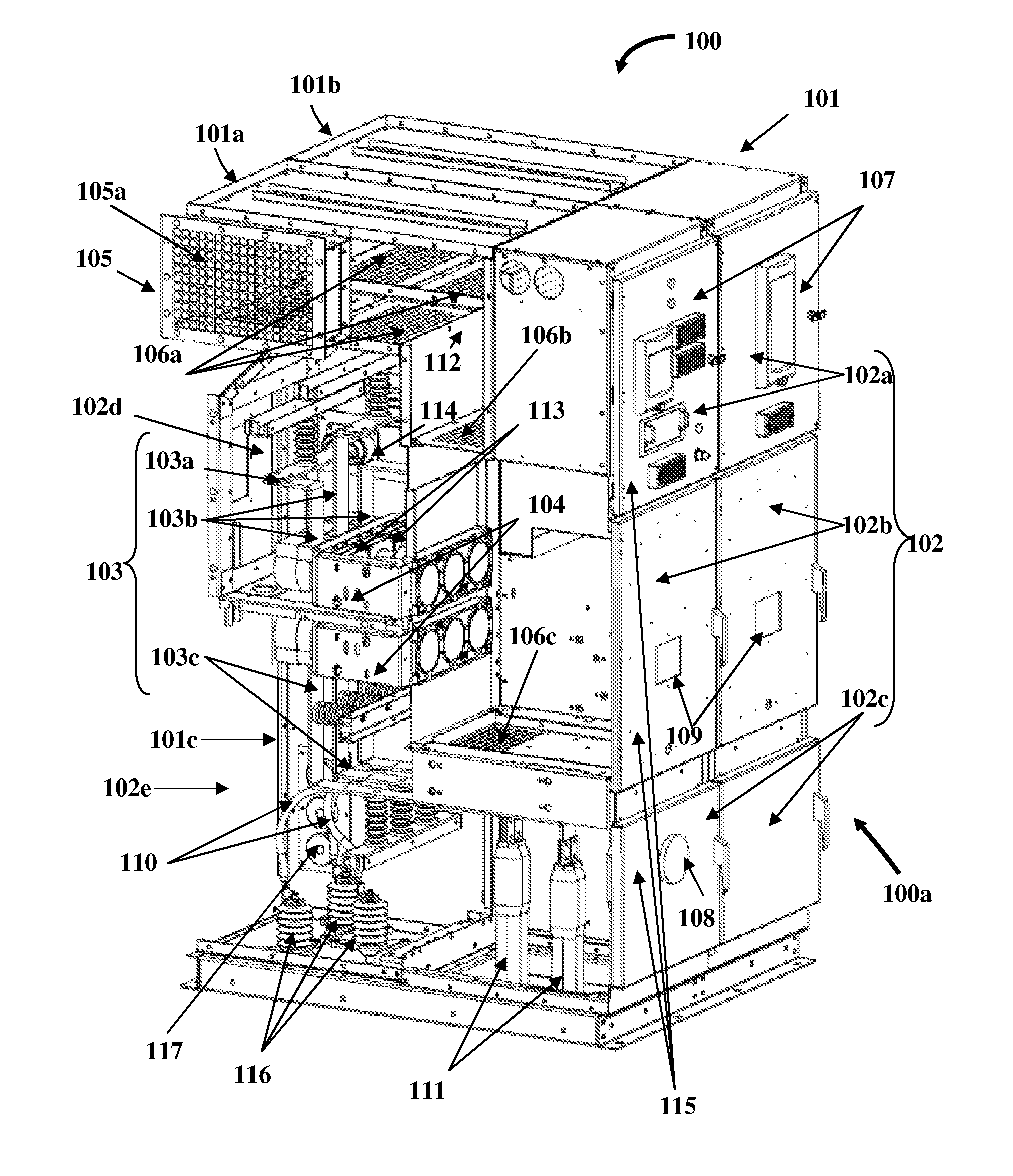
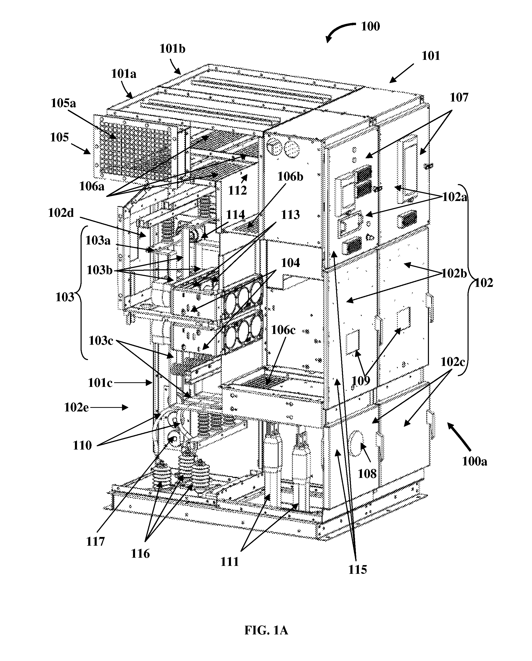
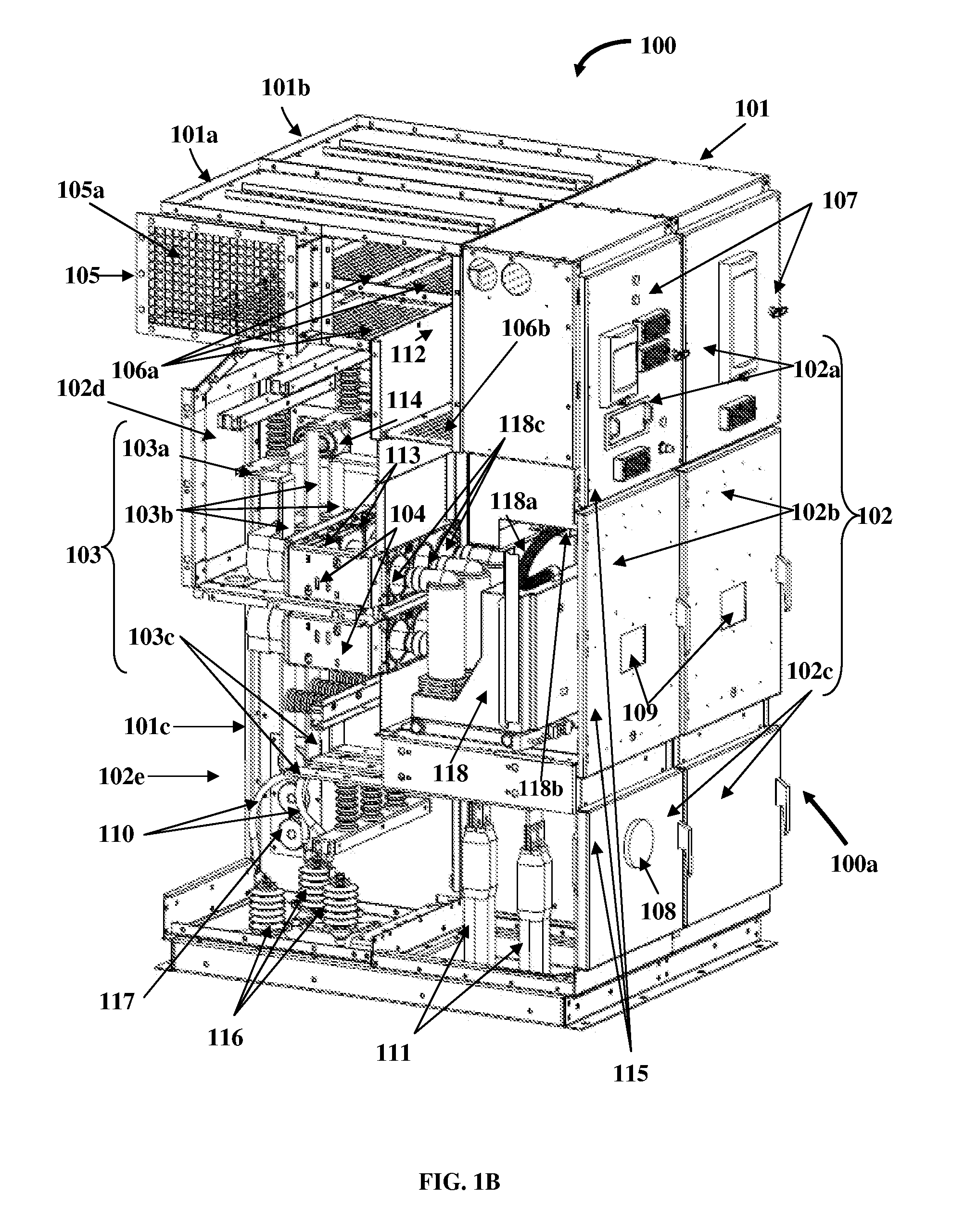
[0056]FIGS. 1A-1B exemplarily illustrate cut-away left perspective views of a front accessible switchgear assembly 100. The front accessible switchgear assembly 100 disclosed herein comprises a compact and arc resistant electrical enclosure 101, multiple compartments 102 defined within the electrical enclosure 101, one or more mounting block assemblies 104, a plenum chamber 105, electrical components 111, 113, 118, 119, 120, etc., and bus bars 103. The front accessible switchgear assembly 100 disclosed herein is a metal clad switchgear assembly. Adjacent sections 101a and 101b defined in the electrical enclosure 101 of the front accessible metal clad switchgear assembly 100 are separated by vertical metal barriers 101c for compartmentalizing active electrical components 118, 119, 120, etc., in the electrical enclosure 101. The front accessible metal clad switchgear assembly 100 has a higher duty cycle and a greater number of load operations, for example, about 10 to about 1000 times...


PUM

PropertyMeasurementUnit
voltageaaaaaaaaaa
voltageaaaaaaaaaa
voltagesaaaaaaaaaa

Abstract

A front accessible metal clad switchgear assembly comprising multiple compartments defined within an electrical enclosure is provided. The compartments interchangeably accommodate electrical components, for example, current transformers, a circuit breaker, a control power transformer, an epoxy encapsulated potential transformer, etc., and bus bars in predetermined positions for allowing front access to the electrical components and bus bars. The front accessible switchgear assembly further comprises a plenum chamber rearwardly positioned in the electrical enclosure and in communication with the compartments to provide an exit path for releasing pressure and gases. A mounting block assembly is positioned in one or more of the compartments for mounting, enclosing, and providing front access to the electrical components. The mounting block assembly is configured to reduce temperature rise in the compartments. Fuse sleeve assemblies operably connected to the control power transformer and the potential transformer allow high voltage primary connections in the electrical enclosure.

Description

CROSS REFERENCE TO RELATED APPLICATIONS[0001]This application claims the benefit of provisional patent application No. 61 / 352,022 titled “Multi-access Switchgear Assembly”, filed on Jun. 7, 2010 in the United States Patent and Trademark Office.[0002]The specification of the above referenced patent application is incorporated herein by reference in its entirety.BACKGROUND[0003]The apparatus disclosed herein, in general, relates to electrical enclosures. More particularly, the apparatus disclosed herein relates to electrical enclosures that provide front access to electrical bus members, multiple electrical components, and apparatuses housed within the electrical enclosures. Furthermore, the apparatus disclosed herein relates to electrical bus assemblies for electrical enclosures and arc resistant electrical enclosures.[0004]Medium voltage electrical components and apparatuses, for example, circuit breakers, potential transformers, current transformers, control power transformers, etc...

Claims


Application Information

Patent Timeline
Patent Type & Authority Patents(United States)
IPC IPC(8): H02B11/00
CPCH02B11/00Y10T29/49105H02B11/26H02B13/025H02B11/04
Inventor MILOVAC, PREDRAGKULKARNI, ASHOK BABURAOROSSI, EDWARD JOSEPHSAPP, DENNIS WAYNE
Owner IEM HLDG GRP INC
Why Eureka
Try Eureka