
Chemical mechanical polishing aqueous dispersion and chemical mechanical polishing method

a chemical mechanical and polishing technology, applied in lapping machines, other chemical processes, manufacturing tools, etc., can solve the problems of difficult depositing of metal in via-holes, erosion, and inability to obtain flat polished surfaces

Active Publication Date: 2013-07-23
JSR CORPORATIOON +1
View PDF29 Cites 14 Cited by
  • Summary
  • Abstract
  • Description
  • Claims
  • Application Information

AI Technical Summary

Benefits of technology

This patent describes a chemical mechanical polishing (CMP) aqueous dispersion used to polish materials containing tungsten, including interconnect layers. The dispersion contains a cationic water-soluble polymer, an iron (III) compound, and colloidal silica particles. The content of these ingredients is important for achieving effective polishing. The CMP method involves using this dispersion for polishing the tungsten film, barrier metal film, and insulating film simultaneously. The technical effect is a more efficient and effective polishing process for materials containing tungsten.

Problems solved by technology

It is difficult to deposit a metal in a via-hole (i.e., fill the via-hole with a metal) in a minute interconnect area of a high-performance integrated circuit.
However, since the above pH range of the polishing composition is not practical when the polishing composition is used to polish a tungsten-containing material, a flat polished surface cannot be obtained when polishing tungsten using the polishing composition having a pH within the above range.
Along with a recent reduction in interconnect width, erosion (wear) that occurs in a minute interconnect area poses a problem with regard to flatness.
It is considered that erosion occurs due to dishing (depression) that occurs in a tungsten interconnect area and thinning (wear) that subsequently occurs in silicon oxide positioned between the tungsten interconnects.
However, since the highly selective polishing composition has a strong effect on a tungsten film, a deterioration in flatness (dishing) may occur in a wide interconnect area, or the surface of the tungsten film may be roughened, for example.
On the other hand, since the nonselective polishing composition does not achieve nonselectivity at a high polishing rate, the polishing rate must be decreased.

Method used


Image

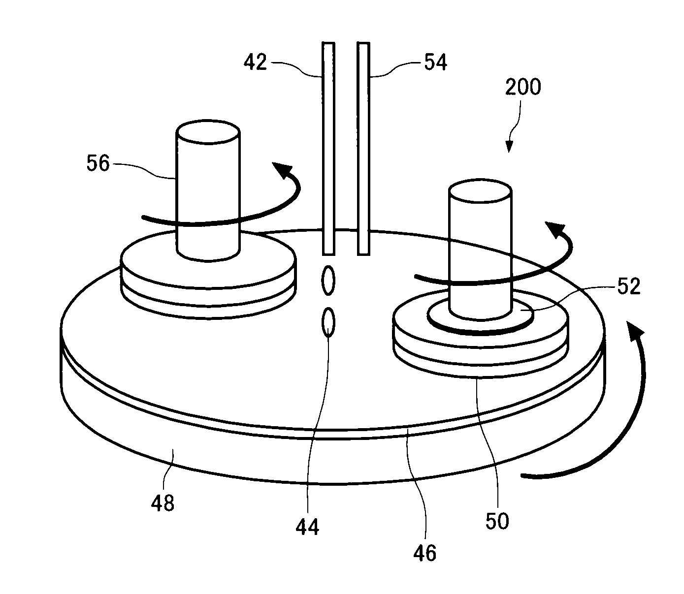
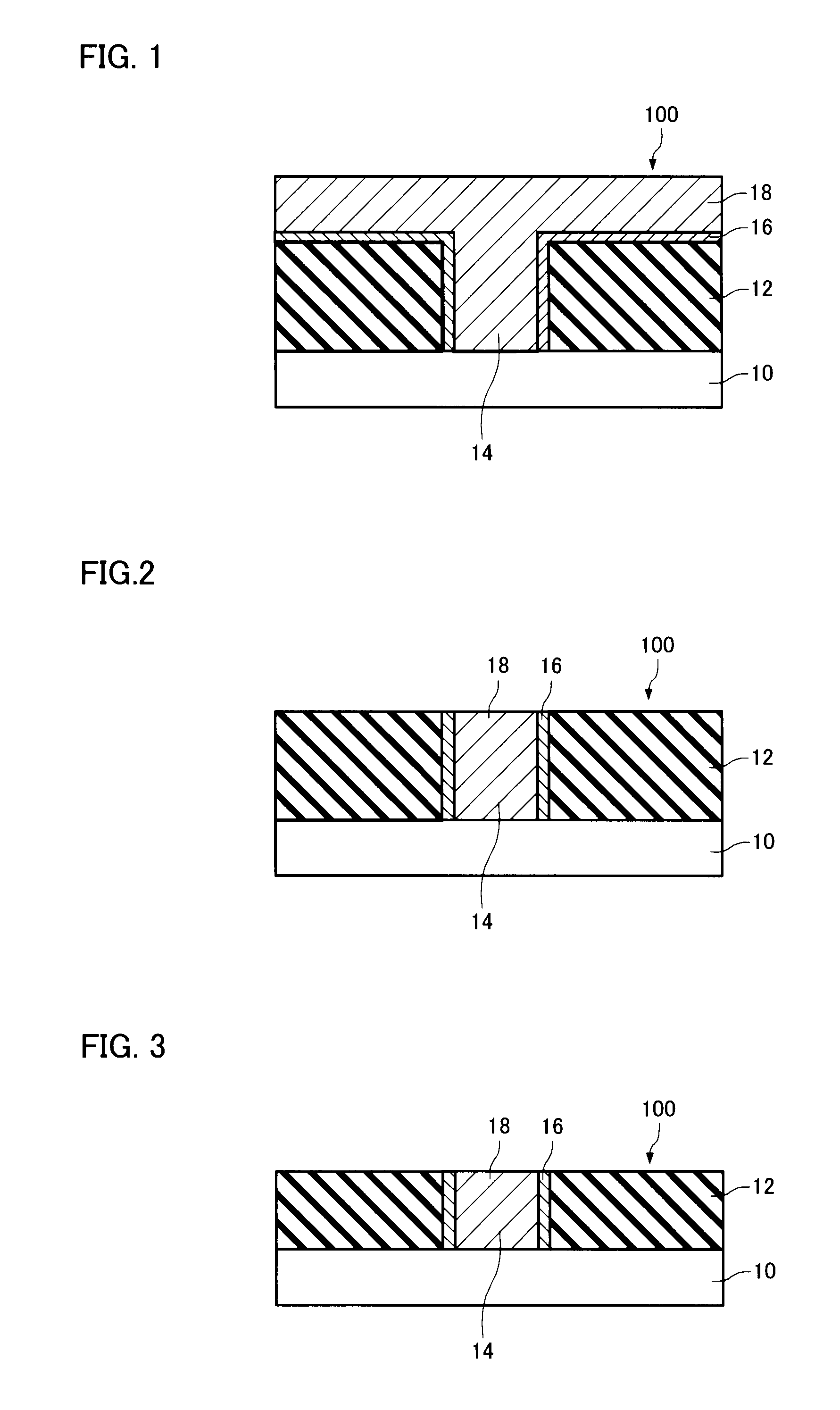
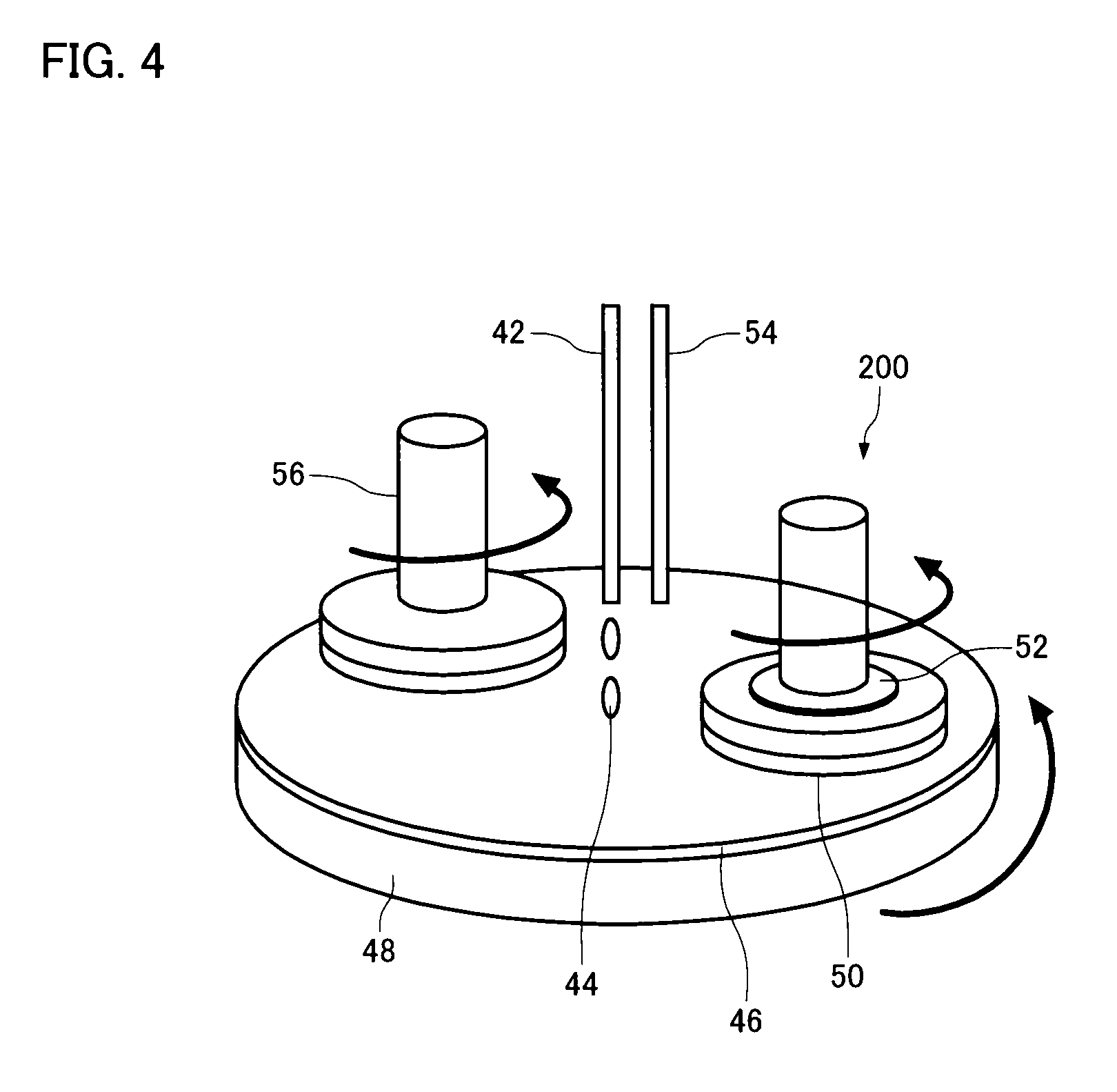
  • Chemical mechanical polishing aqueous dispersion and chemical mechanical polishing method
  • Chemical mechanical polishing aqueous dispersion and chemical mechanical polishing method
  • Chemical mechanical polishing aqueous dispersion and chemical mechanical polishing method

Examples


Embodiment Construction

[0024]The invention may provide a chemical mechanical polishing aqueous dispersion and a chemical mechanical polishing method used to nonselectively polish a tungsten-deposited semiconductor wafer at high speed.

[0025]According to one embodiment of the invention, there is provided a chemical mechanical polishing aqueous dispersion that is used to polish a polishing target that includes an interconnect layer that contains tungsten, the chemical mechanical polishing aqueous dispersion comprising:

[0026](A) a cationic water-soluble polymer;

[0027](B) an iron (III) compound; and

[0028](C) colloidal silica particles,

[0029]the content (MA) (mass %) of the cationic water-soluble polymer (A) and the content (MB) (mass %) of the iron (III) compound (B) satisfying the relationship “MA / MB=0.004 to 0.1”; and

[0030]the chemical mechanical polishing aqueous dispersion having a pH of 1 to 3.

[0031]In this chemical mechanical polishing aqueous dispersion, the cationic water-soluble polymer (A) may be pol...


PUM

PropertyMeasurementUnit
pHaaaaaaaaaa
particle diameteraaaaaaaaaa

Abstract

A chemical mechanical polishing aqueous dispersion is used to polish a polishing target that includes an interconnect layer that contains tungsten. The chemical mechanical polishing aqueous dispersion includes: (A) a cationic water-soluble polymer; (B) an iron (III) compound; and (C) colloidal silica particles. The content (MA) (mass %) of the cationic water-soluble polymer (A) and the content (MB) (mass %) of the iron (III) compound (B) satisfy the relationship “MA / MB=0.004 to 0.1”. The chemical mechanical polishing aqueous dispersion has a pH of 1 to 3.

Description

[0001]The present application claims priority to Japanese Patent Application No. 2008-240851, filed on Sep. 19, 2008, is hereby incorporated by reference in its entirety.BACKGROUND OF THE INVENTION[0002]The present invention relates to a chemical mechanical polishing aqueous dispersion and a chemical mechanical polishing method.[0003]In recent years, interconnects formed in semiconductor devices have been increasingly scaled down along with an increase in the degree of integration of semiconductor devices. In view of such a situation, a chemical mechanical polishing (hereinafter may be referred to as “CMP”) that planarizes various films (metal film and planarization sacrificial film) method that form a semiconductor device by utilizing a chemical effect and a mechanical effect has been used.[0004]Specifically, a conductor metal (e.g., aluminum, copper, or tungsten) is deposited by sputtering, plating, or the like in a minute groove (hereinafter referred to as “via-hole”) formed in a...

Claims


Application Information

Patent Timeline
Patent Type & Authority Patents(United States)
IPC IPC(8): H01L21/302B24B37/00C09K3/14H01L21/304
CPCC09K3/1463C09K13/06H01L21/3212H01L21/7684
Inventor ABE, TAICHISHIDA, HIROTAKATAKEMURA, AKIHIROMENO, MITSURUHIRASAWA, SHINICHIIWADE, KENJINISHIOKA, TAKESHI
Owner JSR CORPORATIOON
Learn More