Cylinder liner and method of manufacturing the same

a technology of cylinder liner and bore gap, which is applied in the direction of machines/engines, foundry patterns, moulding apparatus, etc., can solve the problems of increasing the time for manufacturing cylinder blocks, increasing the and reducing the overall fluidity of block materials, so as to reduce the thickness of cylinder liner and bore gaps, improve bonding strength and thermal conductivity, and minimize the entire size and weight of engines

Active Publication Date: 2013-08-13
YOOSUNG ENTERPRISE +2
View PDF16 Cites 5 Cited by
  • Summary
  • Abstract
  • Description
  • Claims
  • Application Information

AI Technical Summary

Benefits of technology

[0021]Various aspects of the present invention are directed to provide a cylinder liner and a method of manufacturing the cylinder liner, which make it possible to improve bonding strength and thermal conductivity between the cylinder block and the cylinder liner in forming a cylinder block, reduce the thickness of the cylinder liner and a bore gap as much as possible, and minimize the entire size and weight of an engine, by forming a plurality of engraved grooves throughout the outer surface of the cylinder liner.
[0022]Further, another aspect of the present invention is directed to provide a cylinder liner and a method of manufacturing the cylinder liner that make it possible to minimize inferiority ratio of a product by quickly solidifying a block material while considerably reducing the time for manufacturing a cylinder block, by removing factors interfering with the flow of the block material between cylinder liners to improve fluidity of the block material.
[0024]The cylinder liner of the present invention further includes a metal layer for improving thermal conductivity while covering the outer surface of the engraved grooves.
[0034]Further, the method further includes forming a metal layer on the outer surface of the cylinder liner with the plurality of engraved grooves to improve thermal conductivity.
[0043]According to the present invention, it is possible to improve bonding strength and thermal conductivity between the cylinder block and the cylinder liner in forming a cylinder block, reduce the thickness of the cylinder liner and a bore gap as much as possible, and minimize the entire size and weight of an engine, by forming a plurality of engraved grooves throughout the outer surface of the cylinder liner.
[0044]Further, another aspect of the present invention is directed to minimize inferiority ratio of a product by quickly solidifying a block material while considerably reducing the time for manufacturing a cylinder block, by removing factors interfering with the flow of the block material between cylinder liners to improve fluidity of the block material.

Problems solved by technology

However, according to the cylinder liner in the related art, the cylinder liner can be strongly combined with a cylinder block by protrusions formed on the outer surface, whereas the cylinder liner is thick and the size of a bore gap correspondingly increases, such that there is a problem that the size and weight of an engine increase.
Further, the protrusions on the outer surface of the cylinder lines interferes with the flow of the molten metal of a block material that is inserted in the mold, such that there is a problem that the time for manufacturing the cylinder block increases with the decrease of the overall fluidity of the block material and inferior quality may be caused by long-time solidification.

Method used


Image

  • Cylinder liner and method of manufacturing the same
  • Cylinder liner and method of manufacturing the same
  • Cylinder liner and method of manufacturing the same

Examples


Embodiment Construction

[0056]Reference will now be made in detail to various embodiments of the present invention(s), examples of which are illustrated in the accompanying drawings and described below. While the invention(s) will be described in conjunction with exemplary embodiments, it will be understood that present description is not intended to limit the invention(s) to those exemplary embodiments. On the contrary, the invention(s) is / are intended to cover not only the exemplary embodiments, but also various alternatives, modifications, equivalents and other embodiments, which may be included within the spirit and scope of the invention as defined by the appended claims.

[0057]Hereinafter, preferred embodiments of the present invention will be described in detail with reference to the accompanying drawings.

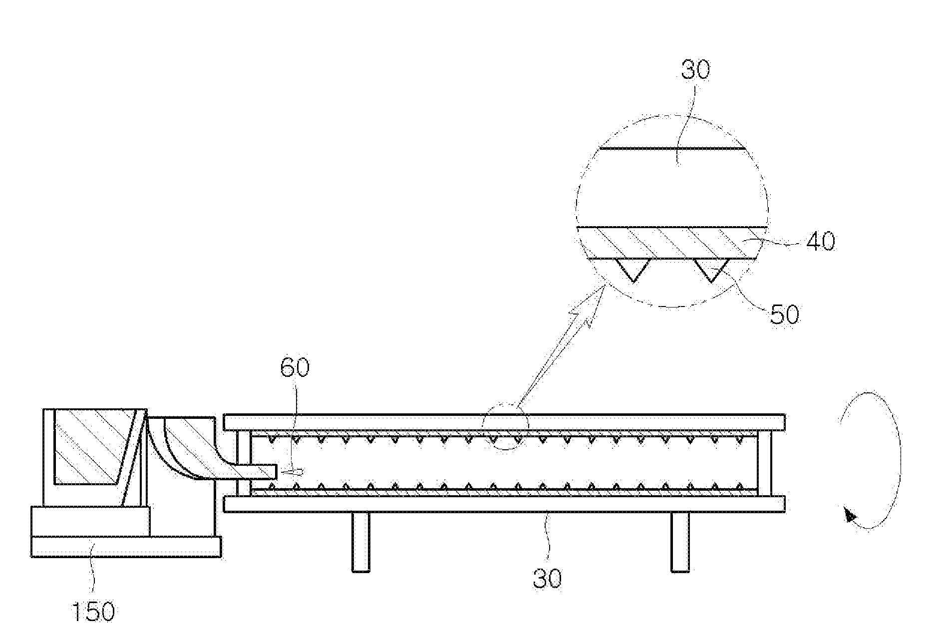
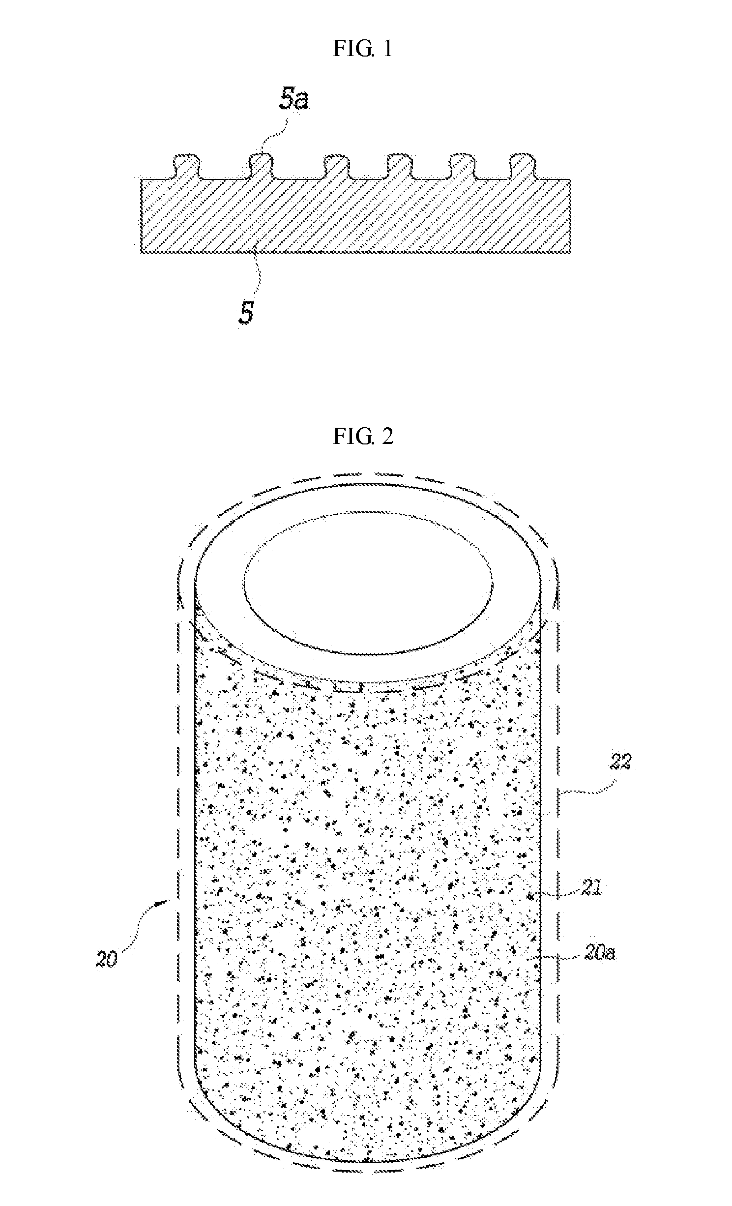
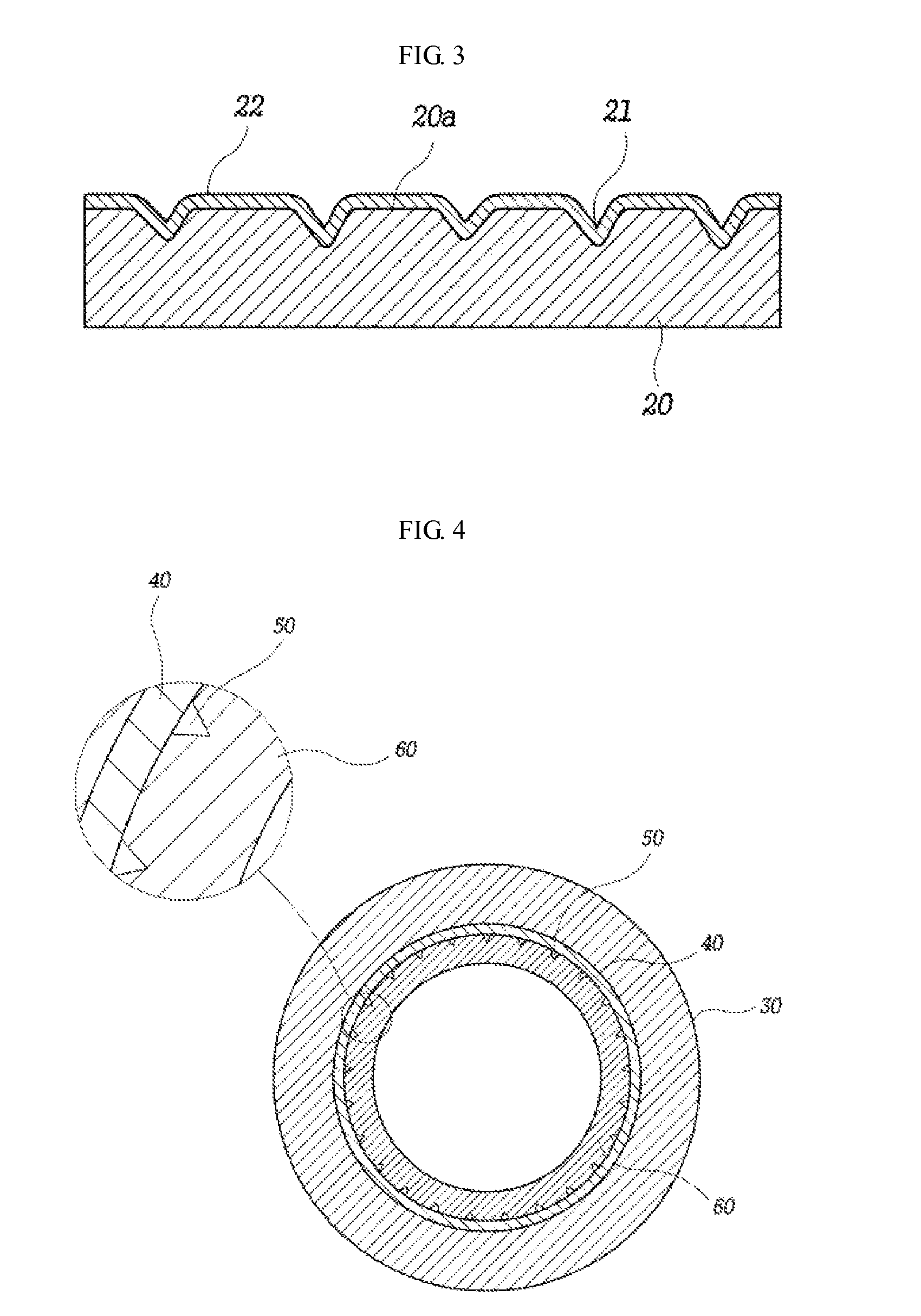
[0058]As shown in FIGS. 2 to 10, a cylinder liner according to an embodiment of the present invention is bonded to a cylinder block 10 for an internal combustion engine, in which a plurality of engr...


PUM

PropertyMeasurementUnit
thicknessaaaaaaaaaa
diameteraaaaaaaaaa
timeaaaaaaaaaa

Abstract

The present invention relates to a cylinder liner and a method of manufacturing the cylinder liner. A cylinder liner according to the present invention has an outer surface covered by casting metal when a cylinder block is manufactured by integral casting, in which a plurality of engraved grooves is formed throughout the outer surface of the cylinder liner to increase bonding force between the casting metal and the outer surface of the cylinder liner. Further, a method of manufacturing a cylinder liner according to the present invention includes: coating a coating material onto the inner circumferential surface of a mold rotating and drying the coating material for a predetermined time; applying an engraved-groove forming material to engrave the surface of the coating material; forming a cylinder liner parent body by pouring and solidifying molten metal through the surface of the coating material where the engraved-groove forming material is applied; and roughening the outer surface of the cylinder liner with a plurality of engraved grooves for spraying, after drawing the cylinder parent body out of the mold and removing the coating material and the engraved-groove forming material covering the outer surface of the cylinder liner parent body.

Description

CROSS-REFERENCE TO RELATED APPLICATIONS[0001]The present application claims priority to Korean Patent Application Number 10-2008-0135601 and 10-2009-0028575 filed Dec. 29, 2008 and Apr. 2, 2009, the entire contents of which application is incorporated herein for all purposes by this reference.BACKGROUND OF THE INVENTION[0002]1. Field of the Invention[0003]The present invention relates to a cylinder liner and a method of manufacturing the cylinder liner.[0004]2. Description of Related Art[0005]In general, cylinders are hollow cylindrical parts in which pistons are guided to reciprocate in internal combustion engines for vehicles. Other than the cylinders used in reciprocating piston internal combustion engines, typical cylinders are cylinders used in reciprocating compressors and cylinders used in oil pressure, hydraulic, and pneumatic machines.[0006]In the reciprocating piston internal combustion engine, an engine equipped with one cylinder is called a single-cylinder engine.[0007]F...

Claims


Application Information

Patent Timeline
Patent Type & Authority Patents(United States)
IPC IPC(8): B22D19/00F16J10/04
CPCB22D13/023F02F1/004B22D19/0009Y10T29/4927
Inventor CHOI, JONGILHAN, SANGDEUKHAN, CHANGBAEPARK, JONGKUAN, GISEOGKIM, JOONGSOOCHO, JINWOO
Owner YOOSUNG ENTERPRISE
Why Eureka
Try Eureka