
Wheel-type ultra high speed railway system

a high-speed railway and wheel-type technology, applied in the direction of machinery control, process and machine control, etc., can solve the problems of high power consumption, reduced efficiency, large air gap between the primary and secondary sides of the linear propulsion motor, etc., and achieves convenient branching, stable traveling, and reduced efficiency

Active Publication Date: 2013-08-13
KOREA RAILROAD RES INST
View PDF26 Cites 12 Cited by
  • Summary
  • Abstract
  • Description
  • Claims
  • Application Information

AI Technical Summary

Benefits of technology

[0028]According to the present invention, there is the advantage of achieving stable traveling up to 400-1000 km / h on a general standard railway section or on a tube railway (low vacuum corresponding to ⅕- 1 / 1000 atmospheric pressure) using a standard railway wheel-type system.
[0029]In particular, the high-speed railway system according to the present invention employs a wheel-type standard railway system, so that a turnout is considerably simplified compared to that of a conventional maglev train, branching is easy, and the range of a closed tube space can be minimized in the case where the present invention is applied to a tube railway and also three or more station turnout railroad tracks can be easily constructed since the turnout occupies a small space, thus being suitable for a mass transportation system including a plurality of vehicles.
[0030]Furthermore, the present invention has better safety than the conventional maglev trains and does not require energy to perform levitation and guidance due to the support of the load by the steel wheels because the vehicle is supported by the steel wheels and a mechanical brake which works in case of an emergency is provided, and can reduce the size of the air gap compared to the conventional maglev trains because the air gap between the onboard electromagnets of the repulsive LSM and the stator coils on the ground can be safely maintained by the tread profile of the steel rails and the wheels, thereby achieving the advantage of improving electrical efficiency.
[0031]Meanwhile, the present invention does not require the T-shaped railroad track (guideway) of the German Transrapid Maglev or the car body-tall vertical walls of the Japanese MLX but instead have only wheel-tall vertical sidewalls and a bottom track structure, so that the present invention provides a transverse section profile most suitable for a circular-shaped tube space, thereby achieving the effect of reducing construction expenses by minimizing the occupied space.
[0032]Furthermore, the conventional maglev trains employ the principle of induction power generation via the air gap between a car body and the ground using an onboard power generator, whereas the present invention enables a circular power generator using the rotation of an axle to be installed based on a minute air gap. Accordingly, the effects of improving electrical efficiency and reducing installation expenses are attained.
[0033]Moreover, the present invention can ensure interoperability for the mutual passage of railway vehicles because existing railways are all standard track gauge wheel-type railways, so that a maintenance train or a rescue train can pass over the railroad of the present invention, with the result that the system of the present invention has considerably higher maintainability and safety than the conventional maglev trains.

Problems solved by technology

In particular, the German Transrapid and the Japanese MLX should employ the above power supply method because a large amount of power is required to perform levitation at low speed or while stopping.
Meanwhile, since the above conventional maglev train systems use a method in which a train levitates and travels without using any support, they are subject to the vertical vibrations of a train, so that the air gap between the primary and secondary sides of a linear propulsion motor should be large.
Since the system employs a normal-conducting method, efficiency decreases because the magnetic flux density is low, so that the power consumption is high.
In order to control the levitation air gap within the error range of ±0.1 mm, the electrical power factor needs to be sacrificed, so that there arises the structural disadvantage of the power consumption increasing because of low electrical efficiency.
From the fact that a rotary motor generally has an air gap in a range of 0.5-1 mm, it can be seen that the efficiency of a linear motor should be poor.
These emergency landing apparatuses still have many problems and have not been thoroughly certified.
In particular, the small-sized emergency wheels do not have a tread profile and a traveling mechanism required by a railway rail-wheel combination, so that the wheels may be damaged or excessive frictional heat may be generated when there is a curve in a landing section.
Moreover, in a high-speed region of 600 km / h or more, the skids may be damaged due to excessive frictional heat.
In particular, when a train is vertically vibrated by shock waves while levitating and traveling, movements which threaten safety may be generated and damage in the form of train coils becoming scratched may occur.
Furthermore, since the railroad track structures of the maglev train systems of FIGS. 1 to 3 have a T-shaped railway or a railway having vertical walls, a large space is required in the tube type system and the construction of the facilities thereof requires high expenses, thereby posing the problem of increasing the required cost.
Furthermore, since a turnout for the conventional maglev trains requires that a heavy railroad track itself has to be moved, it is large in size, requires a long turnout time, occupies a large space, requires that the range of a closed tube space should be significantly expanded in the tube railway, and it is not easy to construct a 3 or more railroad track.
Accordingly, this is an obstacle to the mass transportation system in which a plurality of vehicles is used and traffic is heavy.
Furthermore, since the dispatch of a rescue train in case of an emergency or the passage of a maintenance vehicle is restricted by the complexity of the turnout, there are many difficulties from the point of view of train operation.
Meanwhile, it is difficult to implement a 600 km / h or more high-speed train in a normal open section due to noise and air resistance which increase by the square of the speed of a train in geometric progression when the speed of the train increases.
Furthermore, the adhesive power transmission of the conventional common trains is subject to restraints.
Even when these restraints can be overcome, the general steel wheel-type systems still have restraints resulting from the problem of the rapidly increasing wear of rails and the like.

Method used


Image

  • Wheel-type ultra high speed railway system
  • Wheel-type ultra high speed railway system
  • Wheel-type ultra high speed railway system

Examples


Embodiment Construction

[0043]A wheel-type high-speed railway system according to the present invention will be described in detail below with reference to the accompanying drawings.

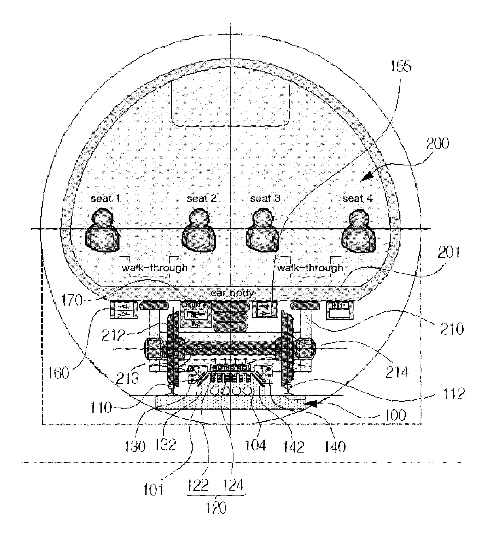
[0044]Here, FIG. 6 is a diagram illustrating the operating principle of a wheel-type high-speed railway system according to the present invention, FIG. 7 is a sectional view showing the railroad track of the present invention, FIG. 8 is a sectional view showing the straight section of the tube-type railroad track of the present invention, FIG. 9 is a sectional view showing the curved section of the tube-type railroad track of the present invention, FIG. 10 is a front view showing the principle parts of the vehicle of the present invention, FIG. 11 is a side view showing the principle parts of the vehicle of the present invention, FIG. 12 is a plan view showing the principle parts of the vehicle of the present invention, and FIG. 13 is a diagram illustrating the control of a vehicle in a turnout section according to the present ...


PUM


Abstract

The wheel-type high-speed railway system includes rails provided on a railroad track and configured such that wheels provided in a bogie of a vehicle come into contact with them, a support provided on a tread surface of a railroad track between the rails, a repulsive Linear Synchronous Motor (LSM) provided between the bogie and the support and configured to improve traveling performance by reducing axle load in a high-speed region, first and second steel plates mounted on both sides of the support in inclined positions, and first and second attractive Dynamic Motion Control (DMC) magnets mounted on the bogie of the vehicle in inclined positions to correspond to the first and second steel plates, and configured to generate attractive force.

Description

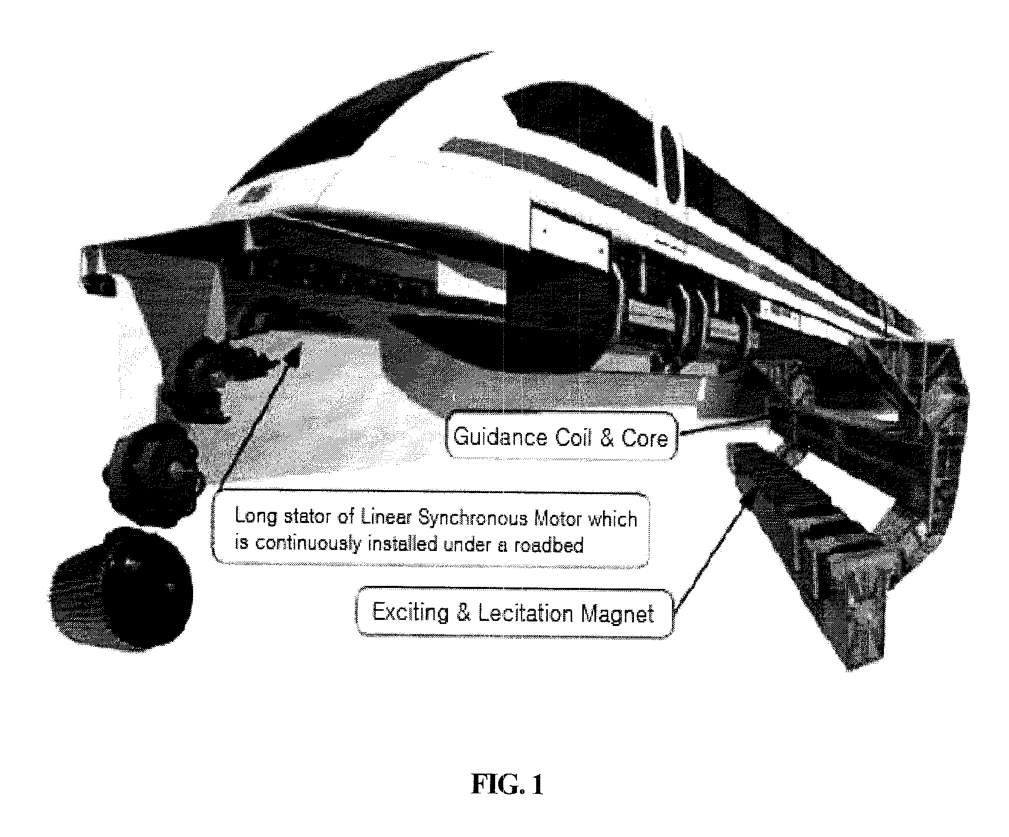
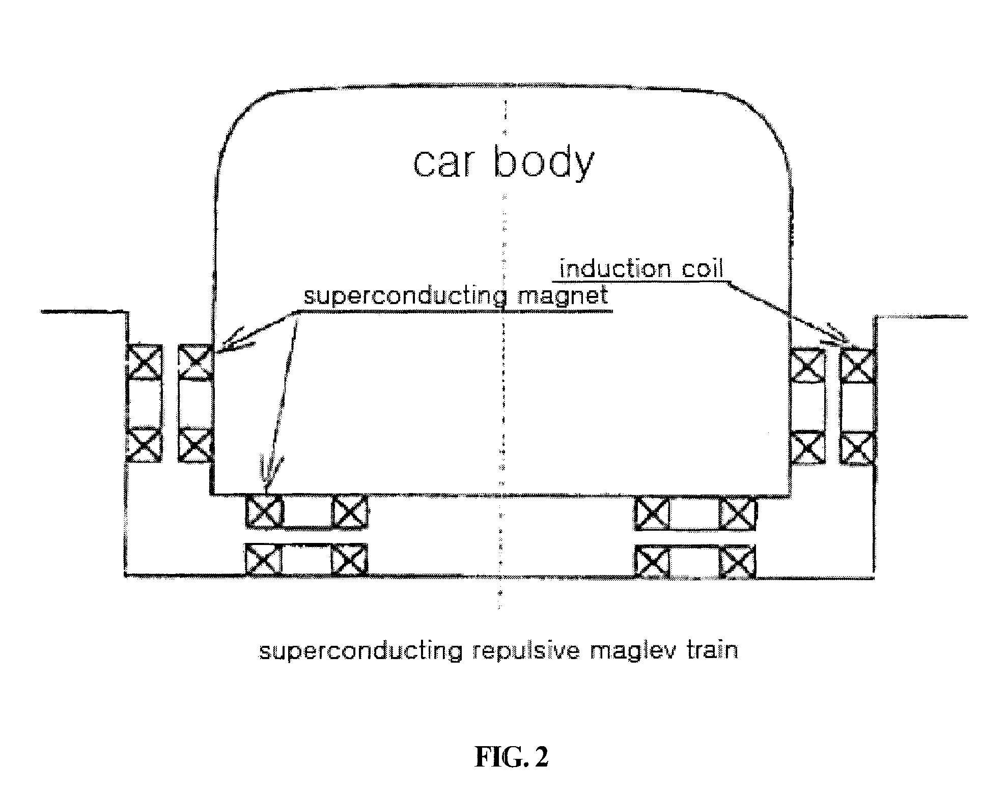
TECHNICAL FIELD[0001]The present invention relates, in general, to a wheel-type high-speed railway system, and, more particularly, to a wheel-type high-speed railway system that enables stable travel at high speed in the range of 400-1,000 km / h even when standard steel wheels for a normal railway are used.BACKGROUND ART[0002]In general, a representative high-speed train system which travels at a speed of 430 km / h or more is a magnetic levitation (maglev) train.[0003]Such maglev train systems include the German normal-conducting attractive-type Transrapid shown in FIG. 1 and the Japanese superconducting repulsive-type MLX Maglev shown in FIG. 2.[0004]The German Transrapid employs a combined levitation propulsion and Linear Synchronous Motor (LSM), and controls a levitation air gap within an error range of ±0.1 mm.[0005]Here, with regard to the supply of onboard power, the German Transrapid and the Japanese MLX receive electricity from a contact-type pantograph while traveling at a lo...

Claims


Application Information

Patent Timeline
Patent Type & Authority Patents(United States)
IPC IPC(8): B60L13/00
CPCB60L13/03B60L13/10B61B13/10B61B13/12B60L2200/26B60L2220/14
Inventor KWON, SAM-YOUNGLEE, HYUNG-WOOPARK, CHAN-BAELEE, BYUNG-SONGPARK, HYUN-JUNECHO, YONG-HYEONKIM, NAM-POYANG, SIN-CHULEE, JUN-SUKKIM, MAN-CHEOLCHOE, KANG-YOUN
Owner KOREA RAILROAD RES INST
Learn More