Constant horsepower regenerative assist for a hydraulic rod pumping unit

a technology of hydraulic rod and regenerative assist, which is applied in the direction of machine/engine, pump control, positive displacement liquid engine, etc., can solve the problems of increasing the number of hydraulic connections which may be subject to failure, and the amount of variation, so as to reduce the size requirements of the drive motor and recover the potential energy stored

Inactive Publication Date: 2013-09-03
WEATHERFORD TECH HLDG LLC
View PDF8 Cites 20 Cited by
  • Summary
  • Abstract
  • Description
  • Claims
  • Application Information

AI Technical Summary

Benefits of technology

[0006]A control unit determines actuation of the pumps for either pumping fluids or providing a hydraulic motor for turning the other pump, in combination with the power output by the drive motor. The control unit includes a microprocessor which controls hydraulic motor displacement for each pump with feedback from pump / motor displacement, pressure transducer and speed sensor. During the up stroke of the well head pumping unit, the accumulator pump is operated as a motor driven by the charge on the accumulator and the control unit increases motor displacement proportional to the pressure decrease in the accumulator charge to maintain a constant output torque or HP to assist the pump even if drive shaft speeds change During the down stroke of the well head pumping unit, the accumulator motor is operated as a pump that charges the accumulator and the hydraulic ram pump is operated as a motor driven by the down stroke rod load that drives the accumulator pump with displacement, pressure and speed feedback that decreases pump displacement proportional to the pressure increase to maintain a constant HP during re-charging of the accumulator. This results in recovery of the potential energy stored by lifting the weight of the sucker rod assembly during the ram up stroke being recovered by passing the hydraulic fluid from the ram through the ram pump in the reverse flow direction, and actuating the ram pump to act as a motor and assist the drive motor in driving the accumulator pump. The power assist provided by using the accumulator pump as a motor results in reducing the size requirements for the drive motor to power the ram pump to drive the hydraulic ram for moving the weight of the sucker rods and associated well fluids.

Problems solved by technology

This results in variations in the amount of sucker rod weight supported by the secondary hydraulic rams during each stroke of the ram pumping unit.
This has resulted in a large number of accumulator containers being present at well heads, also resulting in increasing the number of hydraulic connections which may be subject to failure.

Method used


Image

  • Constant horsepower regenerative assist for a hydraulic rod pumping unit
  • Constant horsepower regenerative assist for a hydraulic rod pumping unit
  • Constant horsepower regenerative assist for a hydraulic rod pumping unit

Examples


Embodiment Construction

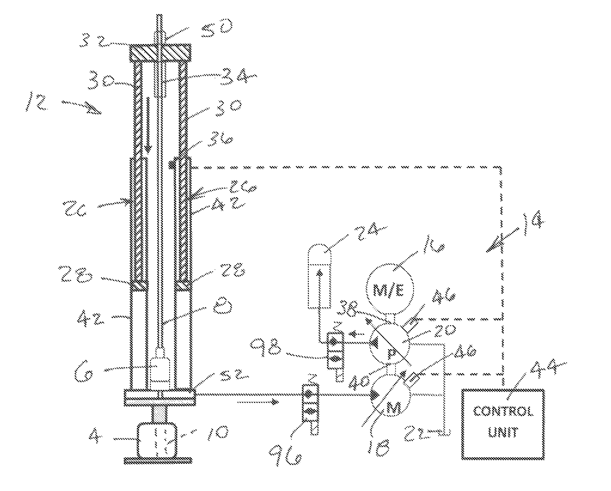
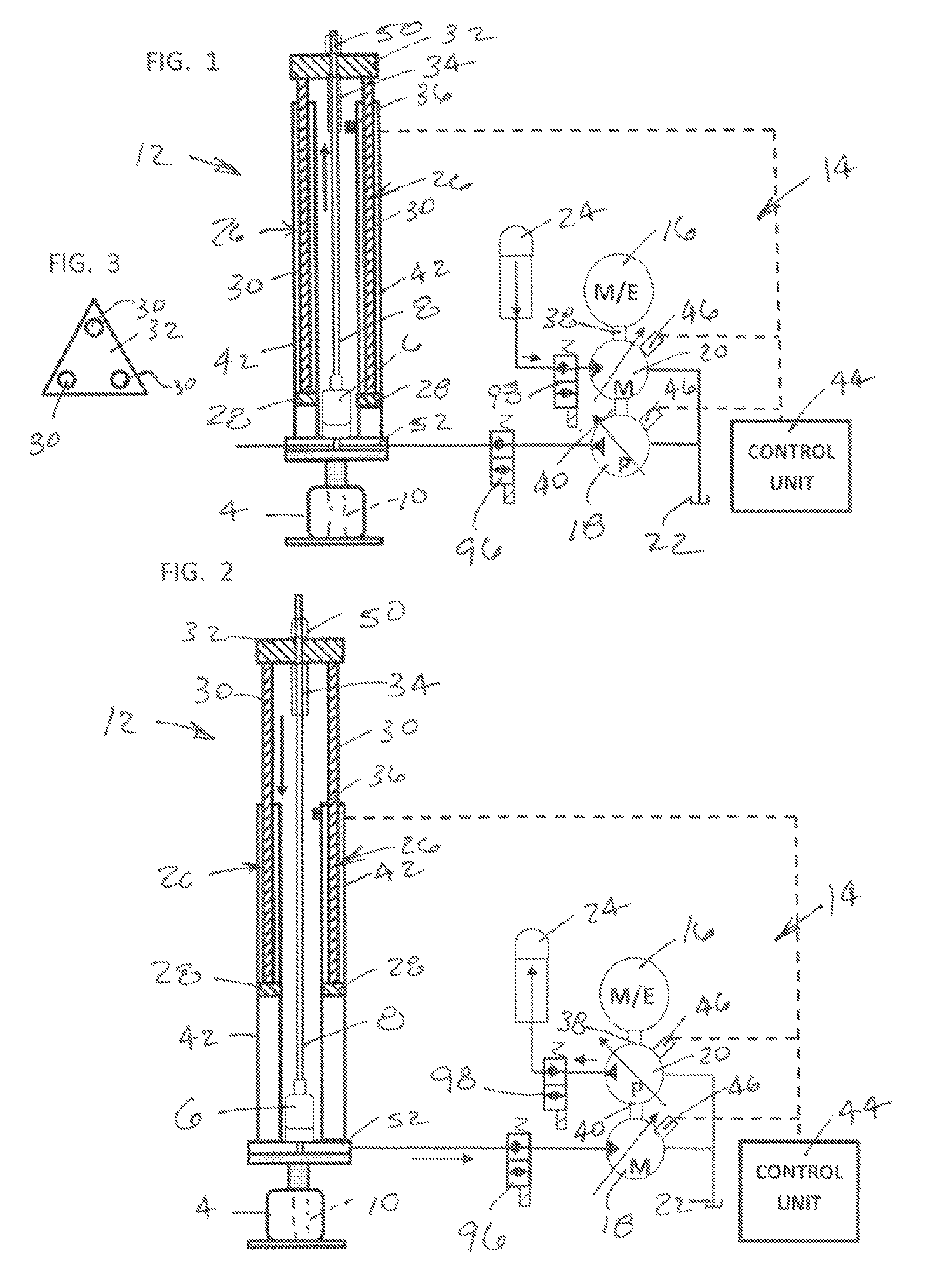
[0012]FIGS. 1 and 2 are a schematic diagram depicting a side elevation view of a hydraulic rod pumping unit 12 having a constant horsepower regenerative assist. FIG. 1 shows the pumping unit in an up stroke, and FIG. 2 shows the pumping unit in a down stroke. The pumping unit 12 is preferably a long stroke type pumping unit with heavy lift capabilities for pumping fluids from a well. The ram pumping unit 12 preferably has three single acting hydraulic rams 26, a sucker rod assembly 10, and a hydraulic power unit 14. FIG. 3 is a partial top view of the hydraulic rod pumping unit 12 and shows the three hydraulic rams 26 connected together by a plate 32 to which the piston rods 30 are rigidly connected. A polished rod 8 is suspended from the plate 32 by a polished rod clamp 50, and extends through a stuffing box 6 for passing into a well head 4 and connecting to sucker rods 10 of a downhole well pump for lifting fluids from the well.

[0013]Each of the hydraulic rams 26 has a guide 28 an...


PUM


Abstract

A hydraulic rod pumping unit (12) has a constant horsepower regenerative assist featuring downstroke energy recovery. The pumping unit (12) has a hydraulic ram (26) connected to a ram pump (18). The drive shaft (40) of the ram pump (18) is coupled to the drive shaft (38) of an accumulator pump (20) and to a rotor of a drive motor (16). A hydraulic accumulator (24) is connected to the output of the accumulator pump (20). The ram pump (18) and the accumulator pump (20) are preferably variable displacement piston pumps which are controlled by a microprocessor based controller (44), such that during the downstroke of the hydraulic ram (26) the ram pump (18) operates as an hydraulic motor powering the accumulator pump (20) and during the up stroke of the hydraulic ram (26) the accumulator pump (20) operates as a hydraulic motor to provide assist to the ram pump (18).

Description

TECHNICAL FIELD OF THE INVENTION[0001]The present invention relates in general to pump units for oil wells, and in particular to a hydraulic pumping unit having a regenerative assist.BACKGROUND OF THE INVENTION[0002]Hydraulic pumping units have been provided for pumping fluids from subterranean wells, such as oil wells. The pumping units have hydraulic power units and controls for the hydraulic power units. The hydraulic power units have an electric motor or a gas motor which powers a positive displacement pump to force hydraulic fluid into a hydraulic ram. The ram is stroked to an extended position to lift sucker rods within a well and provide a pump stroke. The ram lifts the weight of the sucker rods and the weight of the well fluids being lifted with the sucker rods. When the ram reaches the top of the pump stroke, the hydraulic fluid is released from within the ram at a controlled rate to lower the weight of the sucker rods into a downward position, ready for a subsequent pump s...

Claims


Application Information

Patent Timeline
Patent Type & Authority Patents(United States)
IPC IPC(8): F04B49/00
CPCF04B1/32F04B23/02F04B23/04
Inventor BEST, LARRY D.
Owner WEATHERFORD TECH HLDG LLC
Why Eureka
Try Eureka