
High contrast grating based saturable absorber for mode-locked lasers and its applications in passively mode-locked vertical-cavity surface-emitting lasers

a laser mode-locked, absorber technology, applied in semiconductor lasers, laser details, instruments, etc., can solve the problems of insufficient decay time, high cost and complexity of vcsel design, etc., and achieve significant design flexibility and low saturation fluence

Active Publication Date: 2013-09-03
RGT UNIV OF CALIFORNIA
View PDF3 Cites 10 Cited by
  • Summary
  • Abstract
  • Description
  • Claims
  • Application Information

AI Technical Summary

Benefits of technology

The HCG-based saturable absorber offers three times the bandwidth of traditional DBR structures, lower saturation fluence, and integrates lensing effects, reducing the need for separate components, resulting in a more compact and efficient mode-locked laser design suitable for various applications.

Problems solved by technology

A number of materials show some evidence of saturable absorption, yet this only arises at very high optical intensities near the point of optical damage.
When sufficient high incident light intensity is directed at the absorber, atoms in the ground state become excited into an upper energy state at a high rate, such that there is insufficient time for decay to occur back to the ground state before the ground state becomes depleted, accordingly the absorption subsequently saturates.
Mode-locked integrated external-cavity surface emitting lasers have been reported for simplifying the external cavity, however, the cost and complexity of this VCSEL design is often prohibitive.

Method used


Image

  • High contrast grating based saturable absorber for mode-locked lasers and its applications in passively mode-locked vertical-cavity surface-emitting lasers
  • High contrast grating based saturable absorber for mode-locked lasers and its applications in passively mode-locked vertical-cavity surface-emitting lasers
  • High contrast grating based saturable absorber for mode-locked lasers and its applications in passively mode-locked vertical-cavity surface-emitting lasers

Examples


embodiment 1

[0122]2. The apparatus of embodiment 1, wherein said optically absorbing structures comprise any combination of quantum wells, wires and / or dots.

[0123]3. The apparatus of embodiment 1, wherein said optically absorbing structures have a reduced absorption of light with increasing incident light intensity.

[0124]4. The apparatus of embodiment 1, wherein said at least one layer of optically absorbing structures are incorporated between high index of refraction cladding layers within each of said grating elements.

[0125]5. The apparatus of embodiment 1, wherein said at least one layer of optically absorbing structures are incorporated on the surface of said grating elements.

[0126]6. The apparatus of embodiment 1, wherein said grating elements are periodically spaced.

[0127]7. The apparatus of embodiment 1, wherein said grating elements are configured of varying grating element width and / or spacing along their length and / or distribution direction to provide a lensing effect.

[0128]8. The app...

embodiment 9

[0130]10. The apparatus of embodiment 9, wherein said optically absorbing layer inside said high-contrast grating of said apparatus is configured to overlap with areas having the highest electrical field and associated saturation fluence, to reduce the pulse energy at a pulse energy that the absorption saturates.

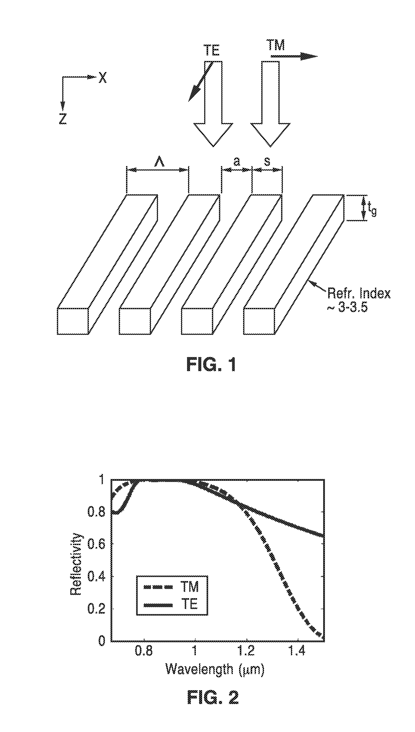
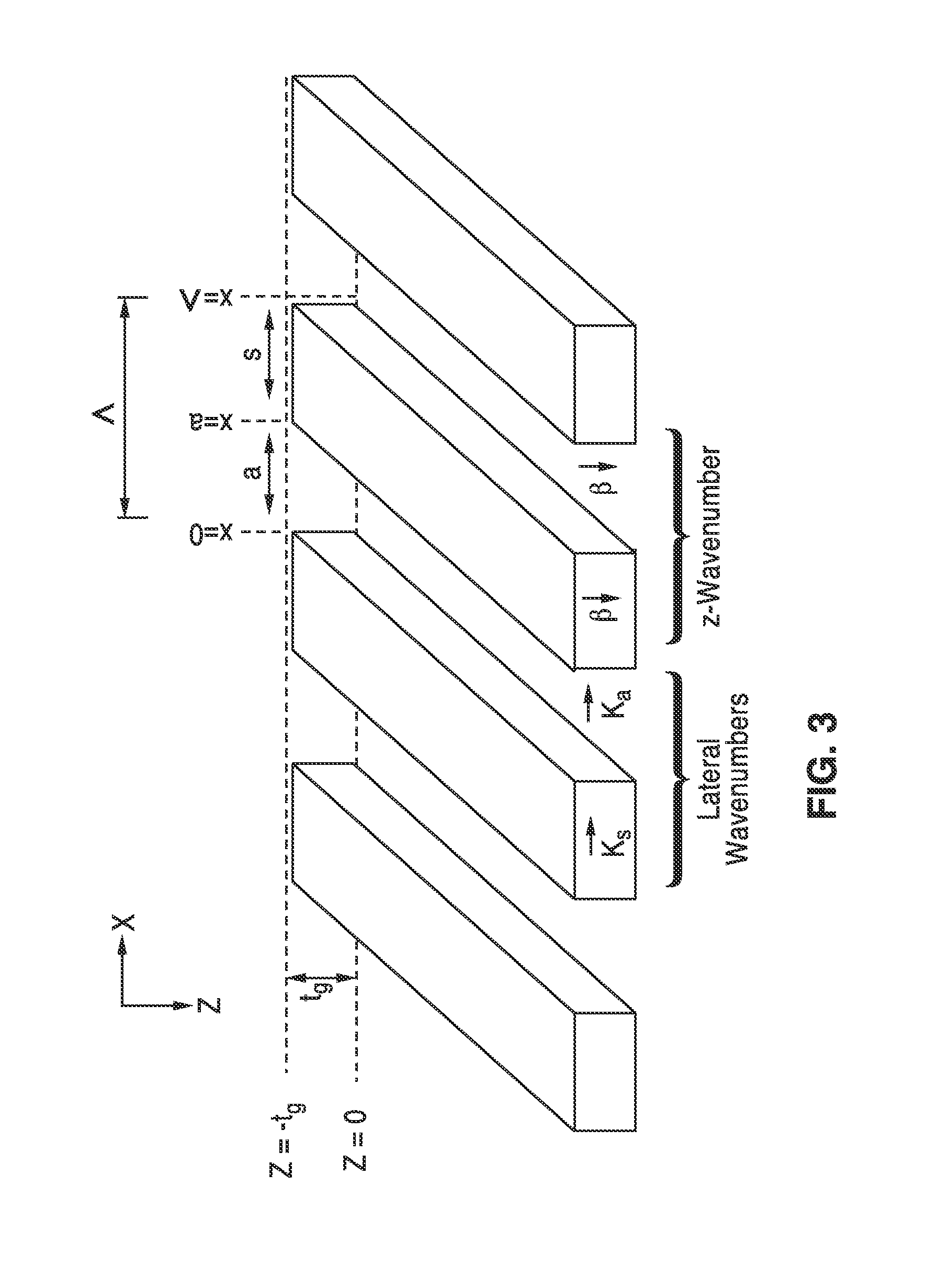
[0131]11. The apparatus of embodiment 1, wherein three physical parameters control reflectivity of the grating, including period (Λ), thickness (tg), and duty cycle (η); and wherein the duty cycle is defined as a ratio between width of the high index material (s) to its period (Λ).

[0132]12. The apparatus of embodiment 1, wherein said apparatus is configured as a mirror within a laser.

embodiment 12

[0133]13. The apparatus of embodiment 12, wherein said apparatus is configured as a mirror within a laser configured for generating short optical pulses.

[0134]14. The apparatus of embodiment 1, wherein said apparatus is configured as a transmissive component within a laser.


PUM


Abstract

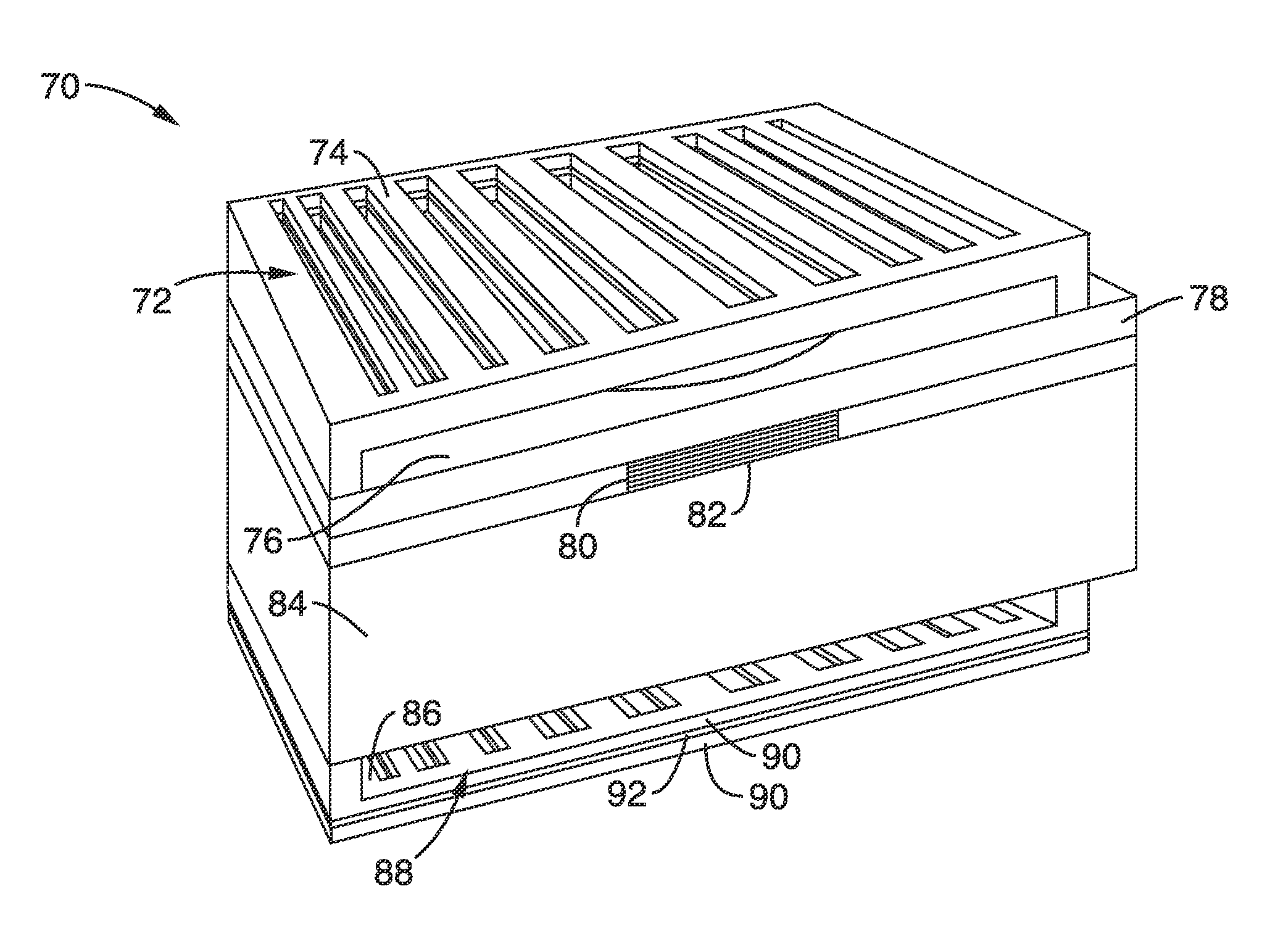
A saturable absorber (SA) based on a high-contrast grating (HCG) having a buried layer of quantum structures for absorption, and which is particularly well suited for use in a mode-locked application. The HCG-SA provides three times the bandwidth compared with traditional DBR structures, while exhibiting a lower saturation fluence due to the field enhancement inside the grating. Varying grating bar width over one or two axis provides lensing effects on the optical output, while chirping of the period and duty cycle changes optical phase relationships. Novel VCSEL embodiments with external or internal cavities are described using the HCG-SA.

Description

CROSS-REFERENCE TO RELATED APPLICATIONS[0001]This application a 35 U.S.C. §111(a) continuation of PCT international application number PCT / US2011 / 026113 filed on Feb. 24, 2011, incorporated herein by reference in its entirety, which is a nonprovisional of U.S. provisional patent application Ser. No. 61 / 307,843 filed on Feb. 24, 2010, incorporated herein by reference in its entirety. Priority is claimed to each of the forgoing applications.[0002]The above-referenced PCT international application was published as PCT International Publication No. WO 2011 / 106554 on Sep. 1, 2011 and republished on Jan. 5, 2012, and is incorporated herein by reference in its entirety.STATEMENT REGARDING FEDERALLY SPONSORED RESEARCH OR DEVELOPMENT[0003]This invention was made with Government support under Grant No. N00244-09-1-0013 awarded by the Department of Defense, and Grant No. Y503161 awarded by the National Science Foundation. The Government has certain rights in this invention.INCORPORATION-BY-REF...

Claims


Application Information

Patent Timeline
Patent Type & Authority Patents(United States)
IPC IPC(8): H01S3/113G02B5/18H01S3/098
CPCG02B5/1809H01S5/18319H01S5/18361
Inventor CHANG-HASNAIN, CONNIEYANG, WEIJIANCHASE, CHRISTOPHERSEDGWICK, FORREST G.
Owner RGT UNIV OF CALIFORNIA
Learn More