
Laser marking method

a laser marking and laser technology, applied in the field of laser marking methods, can solve the problems of high output energy, large size of the resulting mark, and significantly inferior clarity and solidity of the laser marking method, and achieve the effect of effectively preventing counterfeiting of brand name products, high solidity, and easy determination

Active Publication Date: 2016-08-16
SHIZUOKA PREFECTURE +2
View PDF24 Cites 3 Cited by
  • Summary
  • Abstract
  • Description
  • Claims
  • Application Information

AI Technical Summary

Benefits of technology

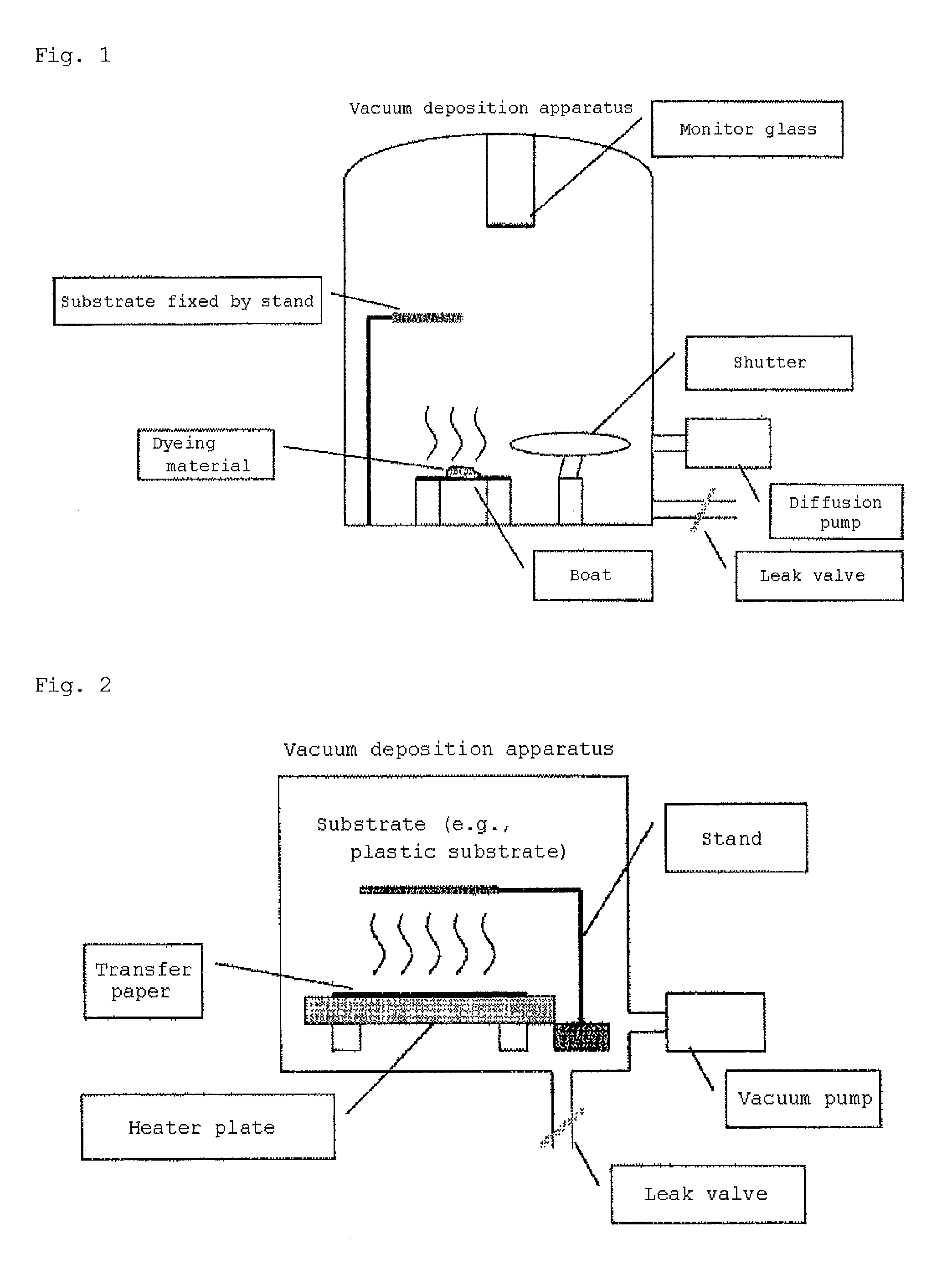
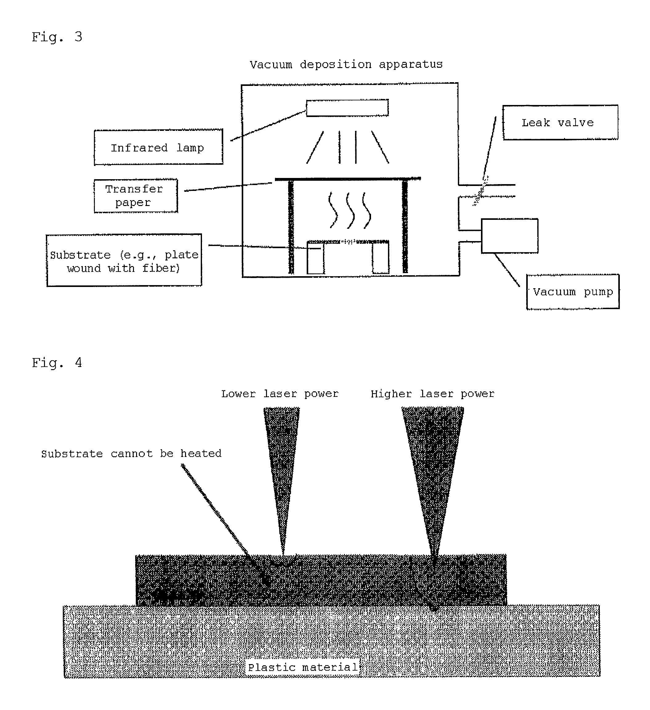
[0109]In the present invention, a very thin coloring material film is formed on a substrate surface by a vapor-phase transfer method, etc., and the substrate surface can thereby be softened or melted with a laser beam even at low output energy and low fluence. This enables the formation of a very minute mark (about 20 μm in size), which was conventionally difficult to form, on the substrate surface. The marking shape can be developed in the desired hue with clarity and high solidity.
[0110]Moreover, since very minute marks, such as letters or symbols, and patterns can be produced on substrates by the method of the present invention, individual yarns can be marked with marks, such as letters and symbols.
[0111]Name-brand products partially or entirely made of the fiber of the invention can be marked with a brand mark or pattern that cannot be discerned by the naked eye but is discernable under a magnifying glass or a microscope, thereby allowing one to easily determine whether marketed products are authentic or counterfeit articles, and thus effectively preventing the counterfeiting of brand name products.

Problems solved by technology

However, the techniques described in PTL 1 and PTL 2 have a fatal defect in that marks formed by the laser marking methods are significantly inferior in clarity and solidity.
In this method, however, the formed coloring-material-containing layer is thick, and therefore, high output energy is required to fix the coloring material in the surface of the substrate by irradiation with a laser beam.
As the output energy of a laser beam increases, the laser fluence also increases; consequently, it is inevitable that the size of the resulting mark becomes larger.
Accordingly, it was difficult, even by the method of PTL 3, to draw very minute letters or patterns (e.g., about 20 μm in width) on substrate surfaces.

Method used


Image

  • Laser marking method
  • Laser marking method
  • Laser marking method

Examples


examples 1 to 12

Experimental Device

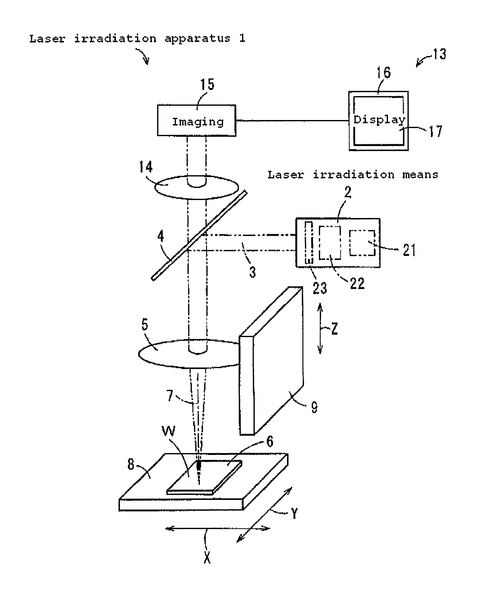
[0136]The laser irradiation apparatus 1 shown in FIG. 6 includes a laser irradiation means 2 integrally comprising a violet laser diode (VLD) as a laser oscillator 21, a collimate lens, and a correcting plate to which wavefront correction had been applied. The emitted light was reflected downward at a right angle with a beam splitter 4 and was focused on the surface 6 of a substrate W by an objective lens 5. The state of the irradiated portion of the surface 6 was then observed by using a measurement means 13.

Disperse Dye and Formulation

[0137]C.I. Disperse Blue 56 (blue), C.I. Disperse Yellow 64 (yellow), and C.I. Disperse Red 60 (red) (disperse dyes; 10 wt. %), 20 wt. % of a dispersant (Demol MS, produced by Kao), and 70 wt. % of pure water were mixed and dispersed to fine particles using a bead mill. The mixture was then suction-filtered through a filter with a pore size of about 1 um (glass fiber filter paper GF / B) to remove large particles, waste, etc. Pure wa...

example 13

[0148]A dye was applied to sheet-like polyethylene terephthalate (PET) substrates and polycarbonate (PC) substrates by the vapor-phase transfer method in the same manner as in Examples 1 to 12 so as to have film thicknesses shown in Tables 2 to 5. The dye used in Example 13 was a disperse dye, C.I. Disperse Blue 56 (blue). Subsequently, the substrates on which the dyes had been applied were irradiated with a laser beam to print the letters “HAMAMATU” in the same manner as in Examples 1 to 12. In this case, the output power of the violet laser diode was about 42 mW, and pulsed wave (PW) was used. The movement speed of the XY stage 8 was 0.3 mm / s. The pulse frequency was 200 Hz, and the duty ratio of the pulse width was 1 / 16. The spot diameter was 8 μm with a half bandwidth. The laser energy was adjusted using filters (30% attenuation filter: AND-50S-30, 50% attenuation filter: AND-50S-50, and 70% attenuation filter: AND-50S-70). Tables 2 to 5 show the relationships between the film t...


PUM

PropertyMeasurementUnit
widthaaaaaaaaaa
thicknessaaaaaaaaaa
widthaaaaaaaaaa

Abstract

This invention provides a laser marking method that can form a very minute mark of a predetermined shape, such as a letter or pattern, with clarity and high solidity, on the surface of a substrate. The laser marking method of the invention comprises the steps of (1) depositing a coloring material on the surface of a substrate of thermoplastic material to form a thin film of the coloring material, and (2) applying a laser beam to the thin film of the coloring material in conformity with a predetermined marking shape to cause the portions of the substrate irradiated with the laser beam to soften and to cause the thus softened portions to mix with the coloring material, thereby developing the predetermined marking shape on the surface of the substrate.

Description

TECHNICAL FIELD[0001]The present invention relates to a laser marking method.BACKGROUND ART[0002]Known laser marking methods are disclosed, for example, in PTL 1 and PTL 2.[0003]PTL 1 discloses forming a clear and hard-to-discolor marked part by laser marking in such a manner that a reaction coloring layer containing a colorant reactive with a laser beam is formed on the surface of a dyeable plastic substrate, a dyeing layer is formed with a combination color that makes the ground color of the coloring layer deeper by dyeing, and marking is performed by irradiation with a laser beam.[0004]PTL 2 proposes a laser marking method in which the surface of a resin molded body is irradiated with a high-energy pulsed laser to mark a pattern, letter, or symbol of any form, wherein a resin powder containing inorganic particles is applied to the surface of the resin molded body, and a laser beam with a pulse of 1 kHz to 50 kHz is applied in conformity with a marking shape, thereby clearly devel...

Claims


Application Information

Patent Timeline
Patent Type & Authority Patents(United States)
IPC IPC(8): B41M5/382B41M5/26B23K26/00
CPCB23K26/0066B41M5/267B41M5/382B41M5/38207B23K26/0006B23K2201/18B23K2203/00B23K2203/42B23K2203/38B23K26/352B23K2101/18B23K2103/38B23K2103/42
Inventor UETA, HIROYASUINUZUKA, MINORUTSUJIMOTO, YUTAKA
Owner SHIZUOKA PREFECTURE
Learn More