Luminaire optical systems

a technology of optical systems and luminaires, applied in the field of optical systems, can solve the problems of not disclosing optical systems, creating unnecessary illumination, and extraordinarily waste of energy, and achieve the effects of improving performance, ensuring ventilation, and efficiently removing heat from the interior of the luminair

Inactive Publication Date: 2013-09-17
STINGRAY ENERGY SYST
View PDF5 Cites 3 Cited by
  • Summary
  • Abstract
  • Description
  • Claims
  • Application Information

AI Technical Summary

Benefits of technology

[0012]The optics of the present systems as are particularly embodied in luminaires such as high bay luminaires disclosed herein preferably include an outer or primary prismatic reflector having concentric scalloping and radial scalloping on interior surfaces, the intersections of such scalloping defining a multiplicity of optically efficient and visually appealing micro-regions. The preferred outer reflector houses an inner reflector movable in tandem with the preferred lamping to vary beam shape and thereby permit adjustability at anytime after original installation of individual luminaires to meet the requirements of a particular application. The inner reflector is preferably formed with radial scallops over its entire surface, preferred scalloping being convex as viewed from “inside” of the reflector. The scalloped inner reflector is preferably provided with a highly specular reflective finish to yield a specular reflectivity approaching 95%. Divergent and convergent profiling of the preferred inner reflector provides particularly improved performance especially with lamping such as high intensity discharge and the like that substantially functions as point source lamping. The inner reflector can be alternatively configured with a wave or concave pattern to provide desired performance.
[0013]Embodiments of the invention particularly useful as high bay luminaires are preferably configured with ventilation apertures formed in upper portions of the outer reflector in order to efficiently remove heat from the interior of the luminaire. Further, the high bay luminaires of the invention are preferably further provided with a prism shield surmounting the outer reflector and formed with ventilation apertures aligned with the ventilation apertures formed in the outer reflector so that ventilation is assured. The prism shiel

Problems solved by technology

Conventional luminaires of these types typically provide uniform illumination over the distribution area of such facilities, such uniform illumination typically being less than adequate for at least certain areas in which a greater degree of light intensity is desirable, such as in an area in which an assembly line is located, as opposed to an area wherein a lesser degree of illumination is necessary such as walkways or the like where tasks requiring greater degrees of illumination are not performed.
Typical high bay or low bay luminaires are incapable of providing adequate lighting levels at these spaced locations within the volumetric confines of a working space or the like without the use of high wattage lamping, thereby creating unnecessary illumination near ceilings in order to create adequate lighting near floor level.
Such conventional luminaires typically use 400 watt lamps as well as lamping ranging up to 1000

Method used


Image

  • Luminaire optical systems
  • Luminaire optical systems
  • Luminaire optical systems

Examples


Embodiment Construction

[0043]The disclosures of U.S. Pat. Nos. 1,286,535; 2,818,500; 3,401,258; 3,800,138; 4,173,037; 4,839,781; 4,903,180; 5,416,684; 5,582,479; 5,791,768; 6,068,388; 6,273,590; 6,464,377; 6,478,454; 6,494,596; 6,698,908; 6,910,785 and 7,025,476 are incorporated hereinto by reference.

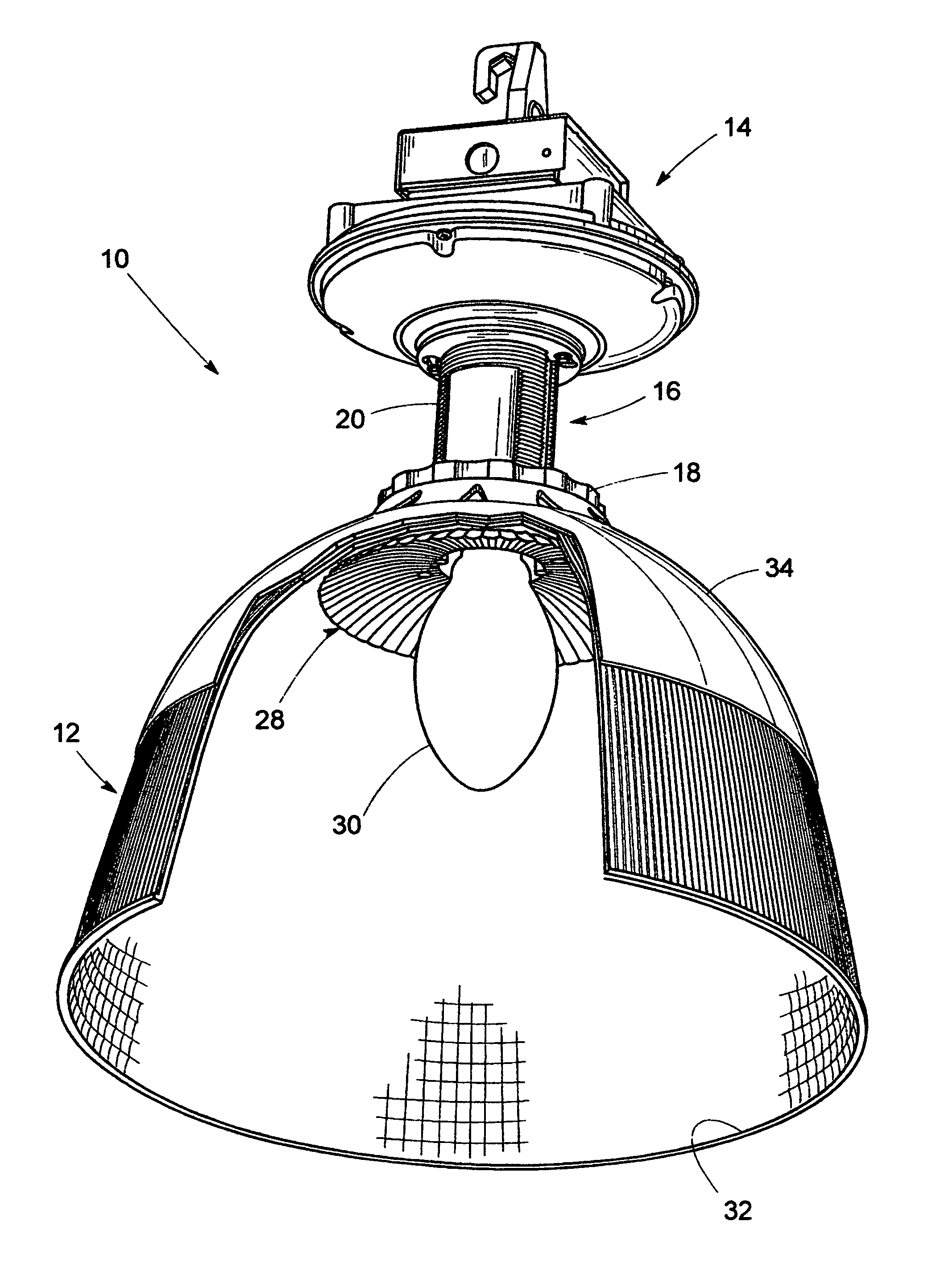
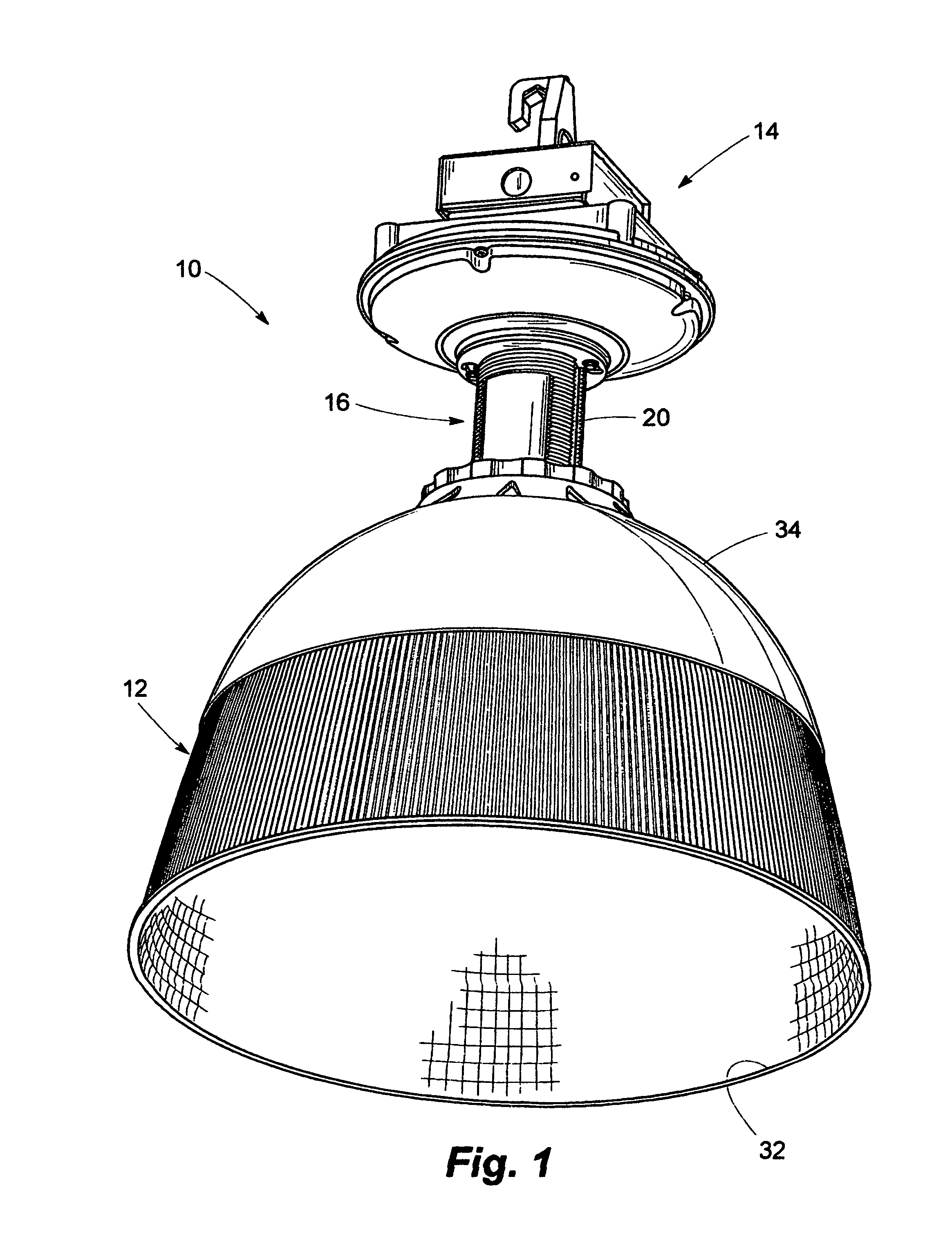
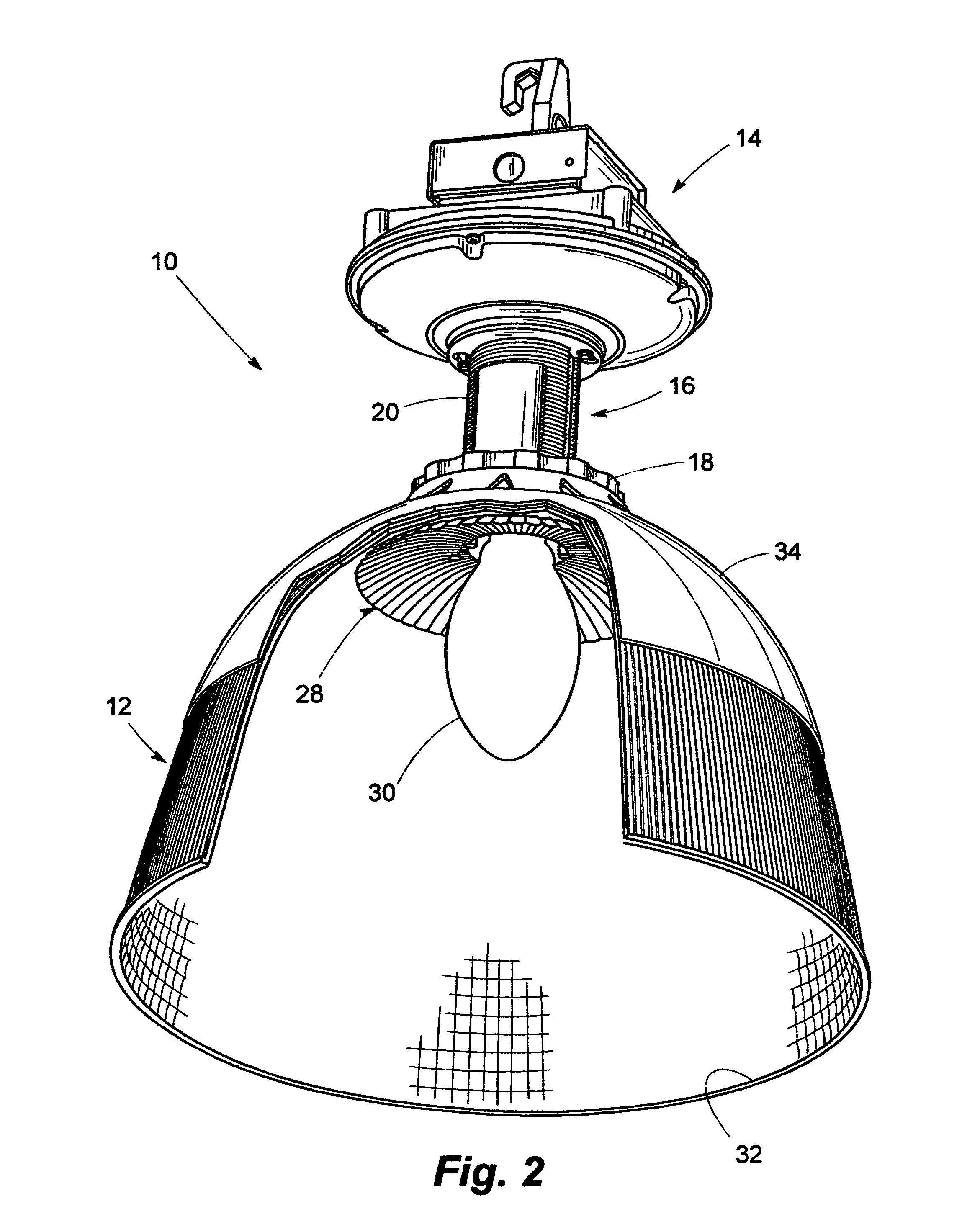
[0044]Referring now to the drawings and particularly to FIGS. 1 through 3, a high bay luminaire is seen generally at 10 to comprise a substantially bowl-shaped outer reflector 12 displaceable within the structure of the luminaire 10 by means of an adjustment mechanism 16, the adjustment mechanism 16 comprising an annular base ring 18 fixed to the outer reflector 12, the outer reflector 12 being displaceable along a threaded tubular adjustment member 20 received within a threaded central bore (not shown) of the base ring 18. The tubular adjustment member 20 is fixedly mounted to a ballast housing 14. Rotation of the outer reflector 12 about the tubular adjustment member 20 displaces the outer reflector 12 rela...


PUM


Abstract

Optical systems capable of use in a variety of lighting applications particularly including industrial high bay and similar applications, the systems of the invention deliver energy efficient and effective light distribution through use of dual reflector arrangements wherein an inner reflector having a divergent and convergent profile is stationary relative to a lamp to form an inner reflector/lamp assembly, a prismatic outer reflector being displaceable relative to the inner reflector/lamp assembly to produce differing photometric distributions.

Description

CROSS REFERENCE TO RELATED APPLICATIONS[0001]This application is a nonprovisional application of Provisional Application Ser. No. 61 / 072,973, filed Apr. 3, 2008, upon which priority is claimed.BACKGROUND OF THE INVENTION[0002]1. Field of the Invention[0003]The invention relates generally to optical systems useful in industrial lighting applications and particularly to energy efficient and high performance luminaires incorporating such optical systems utilizing independent and concentrically aligned reflectors adjustable relative to each other and operating in tandem to produce a versatile range of tailored photometric distributions.[0004]2. Description of the Prior Art[0005]High bay luminaires have traditionally found particular use in warehouses, manufacturing facilities and increasingly in retail situations wherein ceiling heights require lighting adequate for illumination of particular areas within an overall space. Low bay luminaries of similar configuration find utility in ligh...

Claims


Application Information

Patent Timeline
IPC IPC(8): F21V7/00
CPCF21V7/0091F21V5/02F21V29/505F21V29/83
Inventor LEADFORD, KEVIN F.GOULD, CARL T.YATES, JAMES P.
Owner STINGRAY ENERGY SYST
Why Eureka
Try Eureka