
Lighted helmet with heat pipe assembly

Inactive Publication Date: 2013-10-08
MCGINTY PATRICK
View PDF52 Cites 25 Cited by
  • Summary
  • Abstract
  • Description
  • Claims
  • Application Information

AI Technical Summary

Benefits of technology

The present invention provides an improved helmet with a thermal conductive material shell portion that is in thermal communication with a thermal transport system to assist in transporting heat from the scalp of a user. The helmet has a heat dissipating material portion connected to or possibly comprising at least a portion of an exterior shell that may provide the dual function of providing at least a portion of the structural protective shell exterior portion as well as a thermal dissipating surface area for maintaining appropriate operation regarding temperature control of high powered LEDs connected to the helmet. The thermal conductor may also assist in dissipating heat from the head of the user which may be facilitated by having a higher thermal conductivity than traditional helmet material and need not necessarily be a part of the shell for at least some embodiments. One or more heat moving elements can be utilized to assist in transferring heat from the wearer's scalp to the heat dissipating material portion.

Problems solved by technology

The headlight of the '271 patent is not expected to provide significant illumination at a distance.
Even though U.S. Pat. No. 5,871,271 discloses the use of a ten candle power LED: “the headlight or reading function can be enhanced by using high brightness LEDs such as the 10 candlepower white LEDs manufactured by Toshiba Corporation, “high power LEDs are not a viable commercial option at this time.
Furthermore, based on the construction of placing the LEDs in a recess of the hard shell outer layer and not providing any separate heat removal capability as is shown in FIGS. 2, 3a and 3b, a high power LED substituted for a low power LED in that construction would result in burn out almost instantaneously due to the heat buildup and absence of a heat sink (low power LEDs do not normally require a heat sink of any significant size).

Method used


Image

  • Lighted helmet with heat pipe assembly
  • Lighted helmet with heat pipe assembly
  • Lighted helmet with heat pipe assembly

Examples


Embodiment Construction

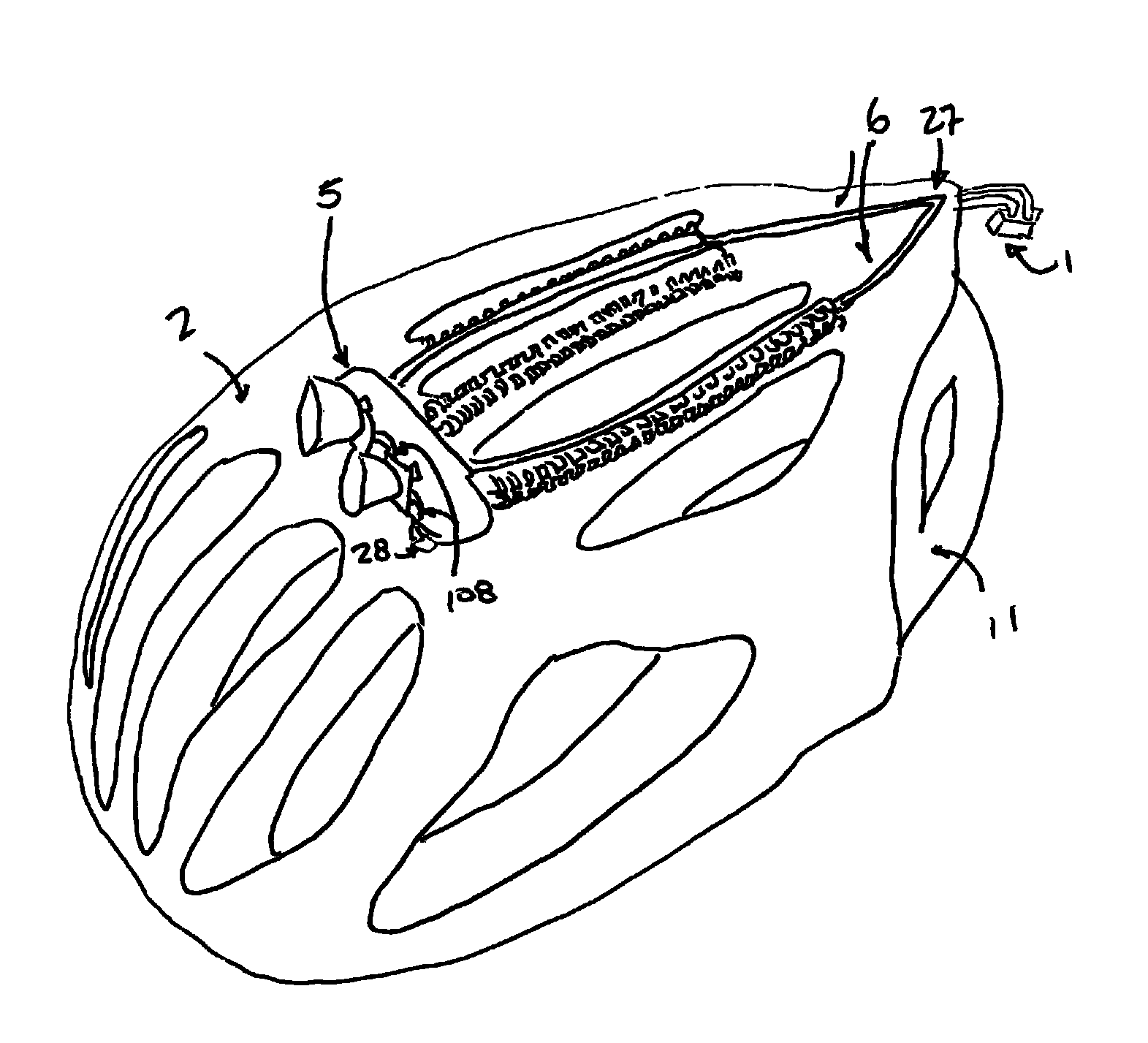
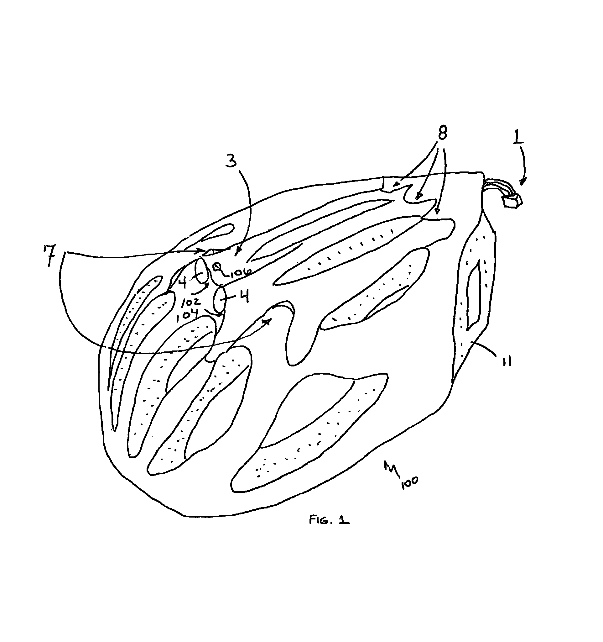
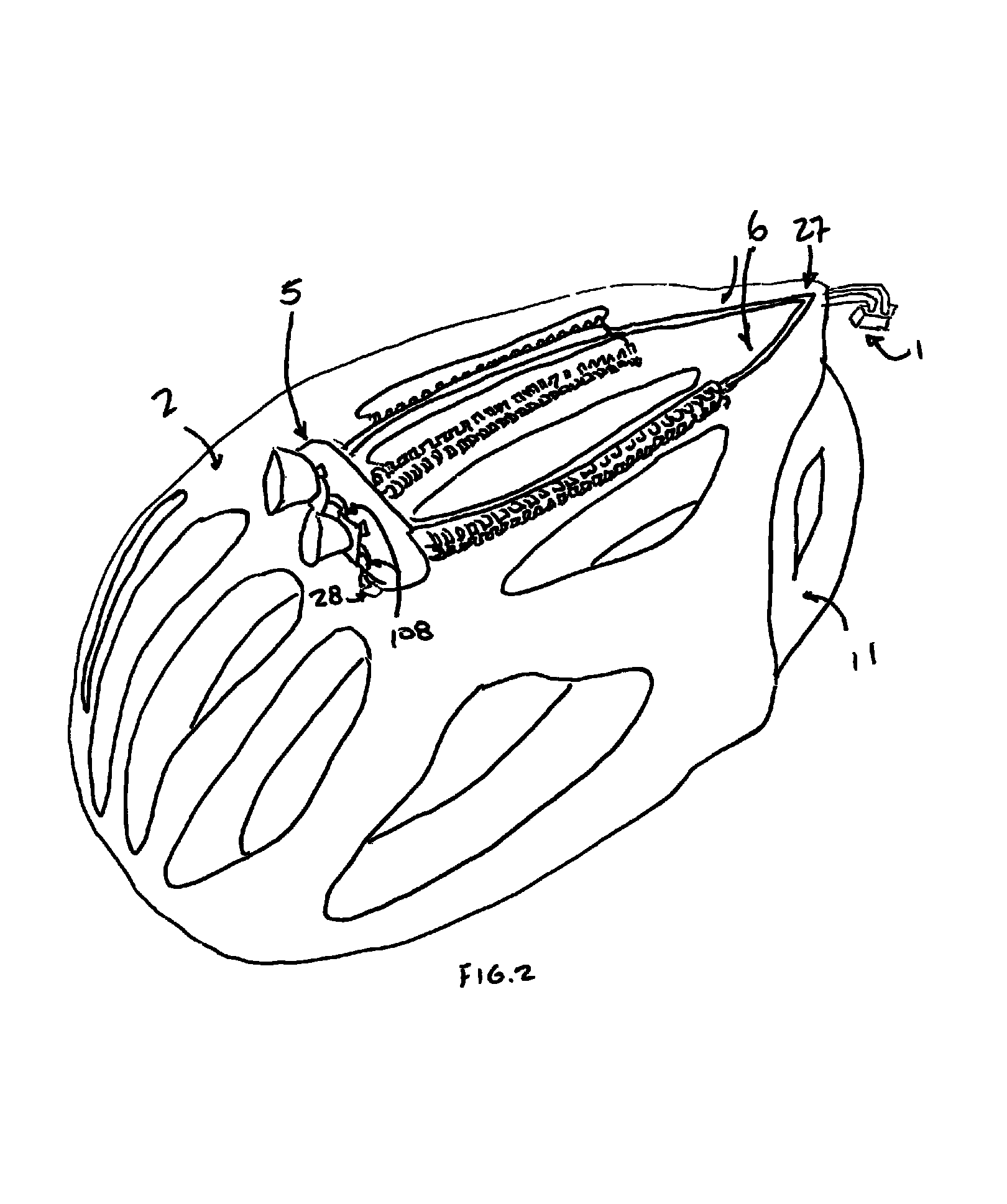
[0030]Helmet 100 of FIG. 1 is preferably constructed to include an outer or primary exterior shell 2 having a heat pipe assembly 5 between the primary exterior shell 2 and the heat pipe shell 3.

[0031]Helmet 100 of FIG. 1 is illustrated as a bicycle helmet, but other safety helmets are contemplated as well in various embodiments. As shown in FIG. 1, the LED optics 4 may be fully protected by the heat pipe shell 3 which also may at least assist in forming the forward facing heat pipe air vents 7. The heat pipe shell 3 may at least assist in completely protecting one or more heat pipes in a heat pipe assembly 5 from blunt and sharp impacts and may have rear facing exhaust vents as illustrated. The primary shell 2 may be intimately adhered to the underlying protective shell 11 which may be made of polystyrene and / or another suitable shock absorbing material. Securing straps are not shown but would be employed for most safety helmets 100 as a harness to firmly hold the helmet on the wear...


PUM


Abstract

A heat dissipating helmet provides a heat dissipating heat pipe portion. One or more high powered LEDs may be in thermal contact therewith providing a significant portion of a heat sink to remove heat from the LEDs to maintain them at a proper operating temperature during operation. The heat dissipating material may be also in contact with air flow as the helmet moves through space thereby allowing convection to assist in removing heat from the helmet.

Description

CLAIM OF PRIORITY[0001]This application claims the benefit of U.S. Provisional Patent Application No. 61 / 372,138 filed Aug. 10, 2010.FIELD OF THE INVENTION[0002]The present invention relates to lighted helmets, and more preferably to a lighted helmet having LEDs utilizing heat pipe technology.BACKGROUND OF THE INVENTION[0003]Lighting on helmets is not new. U.S. Pat. No. 4,195,328 shows an early lighting system providing for an auxiliary headlight to be mounted on a safety helmet 26. The light utilizes a halogen quartz lamp 124 with a reflector 126. In order to address heating concerns, slots 114,118 with a perforated lens cover 116 so as to “permit a dissipation of any internal heat from lighting elements.” Such a heat removal system would probably work for halogen lighting but would not be expected to satisfactory remove heat from a high power LED. Other lighted helmet constructions include U.S. Patent Application Nos. 2008 / 0080171, 2008 / 0170382, 2008 / 026638 and 2005 / 0265015.[0004]...

Claims


Application Information

Patent Timeline
IPC IPC(8): F21V21/084
CPCA42B3/044F21V29/006F21Y2101/02F21Y2115/10F21V29/51
Inventor MCGINTY, PATRICK
Owner MCGINTY PATRICK
Learn More