Estimating direction of arrival from plural microphones

a technology of plural microphones and directions, applied in the field of audio signal processing, can solve the problems of difficult to reduce noise, difficult for these techniques to remove noise without damaging the desired speech, and often loud relative to the desired speech, and achieve the effect of accurately determining the direction of arrival

Active Publication Date: 2013-10-22
CIRRUS LOGIC INC
View PDF17 Cites 36 Cited by
  • Summary
  • Abstract
  • Description
  • Claims
  • Application Information

AI Technical Summary

Benefits of technology

[0028]Another object of the invention is to provide a method and apparatus for more accurately determining direction of arrival in a noise suppression circuit.

Problems solved by technology

Thus, hands free communication is often attempted in harsh, i.e., noisy, acoustical environments such as automobiles, airports, and restaurants.
Moreover, the noise will often be loud relative to the desired speech.
In products with a single microphone, reducing noise is quite difficult when the desired speech and the noise share the same frequency spectrum.
It is difficult for these techniques to remove noise without damaging the desired speech.
The performance of fixed beam former 41 is not sufficient because of beam width, due to side lobes in the beam.
Reverberation also causes problems.
If the adaptive filters are adapting at all times, then they will train to speech from the blocking matrix, causing distortion at the subtraction stage.

Method used


Image

  • Estimating direction of arrival from plural microphones
  • Estimating direction of arrival from plural microphones
  • Estimating direction of arrival from plural microphones

Examples


Embodiment Construction

Basic Technology

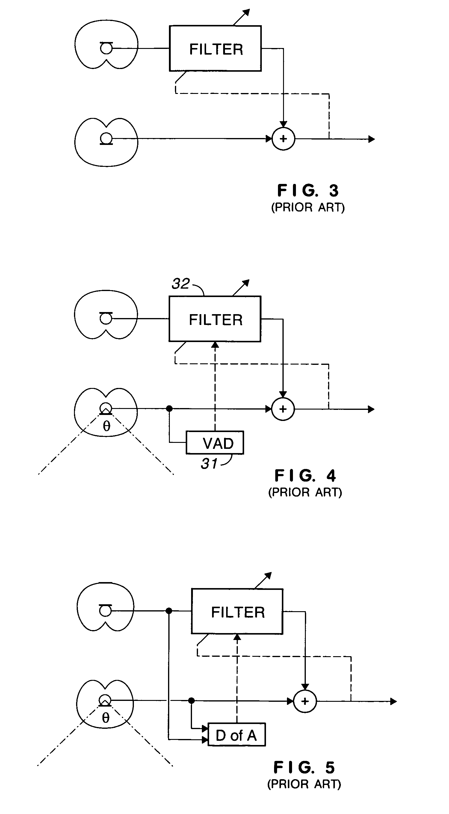
[0044]The direction for arrival is generally estimated by first estimating the time difference of arrival (TDOA) between the sensors. Specifically, for a linear microphone array, if d is the distance between the microphones, direction of arrival θ and time difference of arrival τ are related by

[0045]θ=sin-1⁡(c⁢⁢τd).

where c is the velocity of sound in air, which is equal to 346 m / sec at 77° F. (25° C.).

[0046]Many different techniques are available to estimate TDOA. Some of the techniques include, cross-correlation, absolute magnitude difference function (AMDF), least mean square (LMS), beam-steering, signal energy difference between beam-former / null-former input and output, subspace based methods and blind system identification.

[0047]The cross-correlation based method works by simply computing the cross-correlation between microphones and picking the lag corresponding to the maximum cross-correlation value.

[0048]The AMDF-based method is very similar to the cross-corre...


PUM


Abstract

A noise suppression system includes plural microphones, a fixed beam former, a blocking matrix, plural adaptive filters, and a direction of arrival circuit coupled to the adaptive filters that prevents the filters from adapting in the presence of a signal in the look direction. The direction of arrival circuit causes the filters to adapt more quickly in the absence of a signal in the look direction. A pair of adjustable gain circuits is coupled to each microphone. A first adjustable gain circuit from each pair is calibrated during the presence of a desired signal and a second adjustable gain circuit from each pair is calibrated during the presence of an interfering signal. A fixed null-forming circuit is coupled to a first pair of variable gain circuits and an adaptive null forming circuit is coupled to a second pair of adjustable gain circuits. The ratio of the gains of the null forming circuits is used as a control signal. Successive ratios are averaged with a variable smoothing constant and a control signal is derived from the averaged ratios.

Description

BACKGROUND OF THE INVENTION[0001]This invention relates to audio signal processing and, in particular, to a circuit that estimates direction of arrival using plural microphones.[0002]As used herein, “telephone” is a generic term for a communication device that utilizes, directly or indirectly, a dial tone from a licensed service provider. For the sake of simplicity, the invention is described in the context of a telephone but has broader utility; e.g. communication devices that do not utilize a dial tone, such as radio frequency transceivers or intercoms.[0003]This invention finds use in many applications where the internal electronics is essentially the same but the external appearance of the device is different. FIG. 1 illustrates a conference phone or speaker phone such as found in business offices. Telephone 10 includes microphones 11, 12, 13, and speaker 15 in a sculptured case.[0004]FIG. 2 illustrates what is known as a hands free kit for providing audio coupling to a cellular...

Claims


Application Information

Patent Timeline
Patent Type & Authority Patents(United States)
IPC IPC(8): H04B15/00H04R3/00
CPCH04R3/005H04R3/002H04R2410/01H04R2410/05H04R2430/21H04R2430/23
Inventor EBENEZER, SAMUEL PONVARMA
Owner CIRRUS LOGIC INC
Why Eureka
Try Eureka