Distributed light sources and systems for photo-reactive curing

a distribution light source and photoreactive curing technology, applied in the field of photoreactive curing, can solve the problems of imposing constraints on system design, high heat irradiation from gas discharge lamps, and often considered the most difficult combination of print quality and speed, and achieve the effect of reducing or eliminating the disadvantages of known light sources

Inactive Publication Date: 2013-11-05
EXCELITAS CANADA
View PDF18 Cites 2 Cited by
  • Summary
  • Abstract
  • Description
  • Claims
  • Application Information

AI Technical Summary

Benefits of technology

[0015]The present invention seeks to eliminate, or at least mitigate, the disadvantages of known light sources for UV curing systems, or at least provide an alternative.
[0023]The light source elements may comprise conventional UV lamps, or UV or visible LEDs or LED arrays, for generating visible light or UV radiation of wavelengths suitable for photo-reaction or photo-curing, for applications such as curing of coatings, adhesives, and inks for inkjet or other printing applications. For example, each light source element or sub-assembly may comprise an LED array, e.g. a linear array of 1×n UV LEDs to provide a line or stripe of illumination on a substrate to be cured. By arranging spacing of each LED array to provide first and second regions or zones of irradiation separated by dark zones in which the UV intensity may be relatively low or below threshold for photo-reaction, available power or photon dose may be distributed more effectively to allow dark reactions or dark polymerization, between periods or illumination or irradiation to contribute to effective curing. A distributed arrangement of light source elements may provide more effective use of available energy. Also, a distributed or spaced assembly of a plurality of LED arrays, or groups of LED arrays, may be less expensive, and have reduced cooling requirements relative to expensive, high power, densely packed LED arrays. Such an arrangement may also be preferred for printing or curing on heat sensitive substrates.
[0025]By providing an adjustable arrangement of a plurality of light source subassemblies wherein the relative positioning or spacing of the each can be adjusted, the beam profile may be controlled to provide a pattern of periods of irradiation and intervals for dark polymerization dependent on process parameters, to provide for improved curing efficiency and print quality, for high speed print applications. In some embodiments, the spacing between the light source sub-assemblies also provides advantages for thermal management, and may provide for more efficient cooling. Such an arrangement may be combined with optical elements such as lenses or filters to provide additional control of beam profile and or spacing.
[0031]By setting proper dark intervals, i.e. adjusting the spacing among the distributed light beams, it is possible to have the UV source setup to match the ink chemistry so that UV beams with specific optical profiles can be delivered to control the polymerization reaction to meet the desired / required process speed not only in single pass applications but also in multiple pass applications. Embodiments of the present invention have particular advantages for both scanning type inkjet printers and fixed head digital print applications for high speed printing, or other applications using light sources for photo-curing where a period between illumination or irradiation is not otherwise adjustable.
[0032]In preferred embodiments of the invention, each light source element or sub-assembly comprises at least one UV LED array, for example a linear array of 1×n UV LEDs. Each array may emit at the same wavelength, or one or more arrays may emit different wavelengths, for example to enhance surface curing.
[0034]Although conventional UV light sources, e.g. arc lamps may alternatively be used in such an arrangement, for many applications LEDs have advantages in terms of e.g. size and form factor, efficiency, power consumption, and cooling requirements. Thus, light sources according to preferred embodiments of the present invention provide an additional parameter, i.e. a light source irradiation interval or dark interval between two or more periods of irradiation that is independent of other printer parameters, such as scanning rate, and may allow higher curing efficiency than traditional continuous UV sources. For example, improved curing efficiency may be achieved by matching the irradiation interval to ink chemistry and printing parameters, such as printing speed, which is not available in current digital printing applications. Curing on heat sensitive substrates may also be facilitated.

Problems solved by technology

Among these, the combination of print quality and speed is often considered most challenging.
However, the amount of heat irradiated from gas discharge lamps is usually very high, which places constraints on system design.
Overheating may cause operational and maintenance problems.
Excessive heat also limits the ability of inkjet printers to print on some heat sensitive substrates.
However, if the lamp power is lowered to avoid deleterious heating effects, there may be a trade off, e.g. in lower print quality and speed, or curing may not be achieved at all.
However even with the highest power UV LED chips available to date, inkjet printers that solely use UV LEDs for curing still have some problems such as low print quality and / or speed.
Under some standard print quality examination tests, print samples produced by UV LED inkjet printers may show evidence of improper cure with surface curing problems, adhesion problem, or color bleeding problems.
These arrangements may have difficulty in achieving an intensity that is high enough for good print quality for some applications.
More densely packed LED chips may be provided to achieve high intensity; however liquid cooling may then be required which adds to system complexity and cost.
Such UV LED heads are very expensive because of the density and large number of LED chips required.
This type of focused beam may be overkill, i.e. delivering a high intensity over a short period of time may result in low curing efficiency.
For reasons mentioned in copending U.S. patent application Ser. No. 12 / 582,492, “System, method, and adjustable lamp head assembly for ultra-fast UV curing”, while light intensity must be greater than a threshold to initiate photo-reactions, high intensity irradiation may exceed a saturation value, above which light is not utilized efficiently for photo reactions or photo curing.
For example, for scanning type inkjet printers with continuous irradiation, although the ink layers may receive multiple UV illuminations (i.e. multiple scans), the period between each illumination is determined e.g. by the configuration of the print engine and one or more light sources, and scanning rate, for the print process and usually does not provide the flexibility of adjustment to match the optimal UV irradiation requirements by the ink chemistry.
The period between each two illuminations may not effectively match the dark reaction requirements of the ink chemistry.
In systems providing a focused single beam, such UV sources also do not take advantage of dark reactions effectively.
These systems do not provide sufficient control of periods of irradiation vs. dark polymerization for optimizing or improving the cure efficiency.
However, for some applications this solution may not be suitable, or too complex, and alternative or simpler, lower cost solutions may be required.
Also even if the intensity and beam profile of a light source may be adjusted, it does not overcome the disadvantage mentioned above that in scanning type inkjet printers, the period between scans is fixed and dependent on the apparatus and cannot provide control over an interval of dark polymerization between periods of irradiation.
Thus known UV curing systems such as inkjet printers, and particularly scanning type inkjet printers, may not provide sufficient control of the spatial pattern of irradiation, and dark intervals, leading to problems with print quality or curing efficiency for some applications.

Method used


Image

  • Distributed light sources and systems for photo-reactive curing
  • Distributed light sources and systems for photo-reactive curing
  • Distributed light sources and systems for photo-reactive curing

Examples


Embodiment Construction

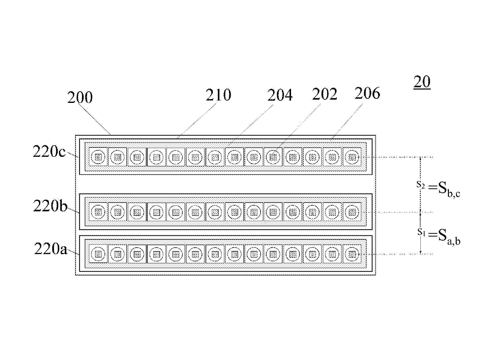
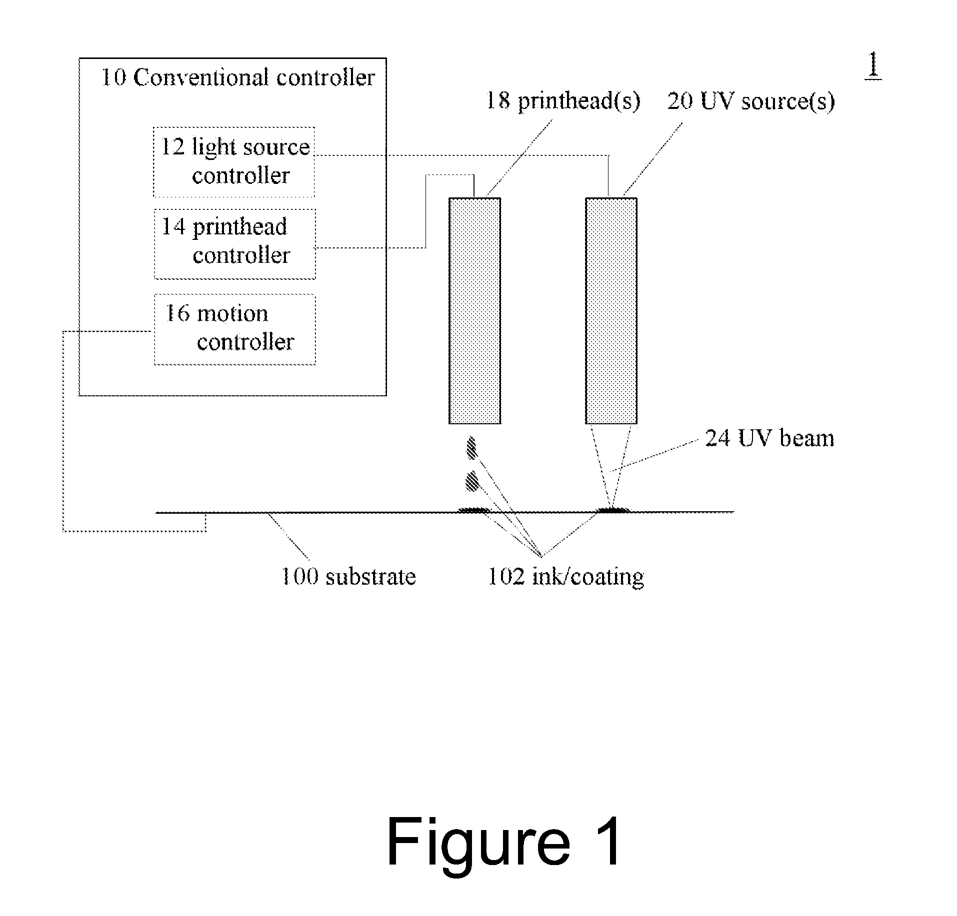
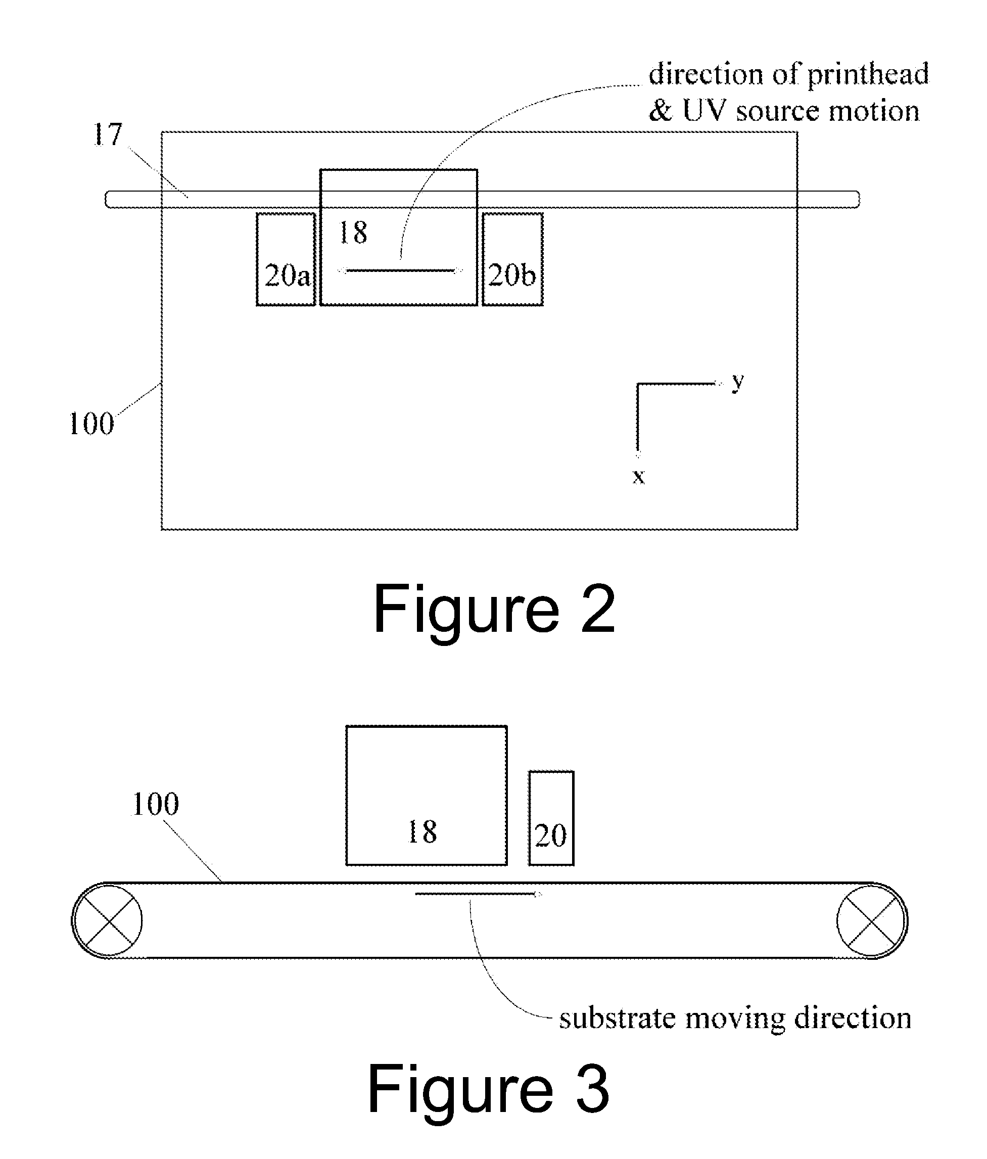
[0049]Light sources according to embodiments of the present invention may be used in a UV curing system, and in particular a UV inkjet printer or recording apparatus, such as illustrated schematically in FIGS. 1, 2, and 3. Light sources 20 according to embodiments of the present invention will be described in more detail with reference to FIGS. 4 to 9.

[0050]FIG. 1 shows a simplified schematic diagram of elements of a typical UV curing system 1 for use in digital printing applications. The system comprises at least one print head 18 for jetting ink or coating 102 onto a substrate 100 and at least one light source unit or lamp head 20, which comprise one or more light sources sub-assemblies 220a . . . 220n, as will be described with reference to FIGS. 4 to 9, for generating a UV beam 24 with a desired wavelength and beam profile to illuminate, or irradiate, an area of the coating / substrate 102 / 100 to cause photo-reaction or photo-curing of the ink and coating 102 on the substrate 100....


PUM


Abstract

A light source for a photo-reactive curing apparatus is provided, which includes a plurality of light source elements or modules, such as, UV or visible LEDs or LED arrays, arranged to provide a beam profile comprising irradiation zones separated by a dark zone. Photo-polymerization occurs during periods of irradiation and dark polymerization occurs during dark intervals between irradiation. The relative positioning or spacing of light source elements or modules is set to provide an exposure profile with a dark interval which matches the required dark reaction interval for optimal curing efficiency. In modular or adjustable light sources, the spacing is adjustable dependent on process parameters. For processes such as inkjet printing, the beam profile may be better matched to the ink chemistry, so as to control the polymerization reaction to meet a required process speed for single pass or multiple pass applications.

Description

CROSS-REFERENCE TO RELATED APPLICATIONS[0001]This application is a continuation application of PCT Application No. PCT / CA2010 / 000411, entitled “Distributed Light Sources for Photo-reactive curing”, filed Mar. 17, 2010, designating the United States, which claims priority from U.S. Provisional Application No. 61 / 161,281 of the same title, filed Mar. 18, 2009, and is related to U.S. application Ser. No. 12 / 582,492 entitled “System, Method and Adjustable Lamp Head Assembly for Ultrafast UV Curing”, filed Oct. 20, 2009, all of which are incorporated herein by reference in their entirety.TECHNICAL FIELD[0002]This invention relates to photo-reactive curing of inks, coatings, and other photoreactive materials, and particularly to light sources and systems for improved curing efficiency and print quality for high speed print applications.BACKGROUND[0003]Many inks, adhesives and other curable coatings comprise free radical based or cationic formulations which may be photo-cured by exposure t...

Claims


Application Information

Patent Timeline
Patent Type & Authority Patents(United States)
IPC IPC(8): B41J2/01G01D1/00B41J2/47B41J2/435
CPCB41J11/002B41J11/00212B41J11/00214
Inventor YANG, GUOMAOPENG, SHENG
Owner EXCELITAS CANADA
Why Eureka
Try Eureka