Compact isocentric gantry

a compact isocentric, gantry technology, applied in the field of proton therapy, can solve the problems of acute short-term complications, short-term and later-stage tumors in long-term cancer survivors, and normal tissue, and achieve the effect of facilitating beam scanning

Active Publication Date: 2013-11-05
PRONOVA SOLUTIONS
View PDF7 Cites 31 Cited by
  • Summary
  • Abstract
  • Description
  • Claims
  • Application Information

AI Technical Summary

Problems solved by technology

The central challenge to modern radiation therapy is to enhance local tumor control using dose escalation and to minimize the dose to normal tissues in order to improve survival and the quality of life of the patients.
Radiation can damage normal tissue and thus causes both short term and later stage tumors in long-term cancer survivors.
Yet, acute short term complications do occur and are still the limiting factor for some treatments.
More insidious for younger patients is the long term potential occurrence of secondary tumors for years and even decades after the treatment.
Such effects also have substantial costs associated with their treatment that may continue for many years after treatment.
One of the major roadblocks to the greater application of proton therapy is that of cost.
The capital cost of a proton therapy center is due both to the cost of the very large equipment and of the heavily shielded vaults in which it is installed.
While beam scanning upstream of the last gantry dipole did effectively reduce the treatment nozzle it also resulted in a very large, heavy gantry and included a costly 90 degree bend magnet weighing about 90 tons.
However, at that time it was concluded that complexity of the cryogenic system and difficulty of ramping the superconducting magnets would make the application of low temperature high field magnets technically overly challenging.
Unfortunately, this also resulted in a very large, heavy (about 90 tons), and costly 90 degree bend magnet.
However, such a gantry remains very large.
Additionally, the gantry requires a significant increase in the number of magnetic elements in the gantry system.

Method used


Image

  • Compact isocentric gantry
  • Compact isocentric gantry
  • Compact isocentric gantry

Examples


Embodiment Construction

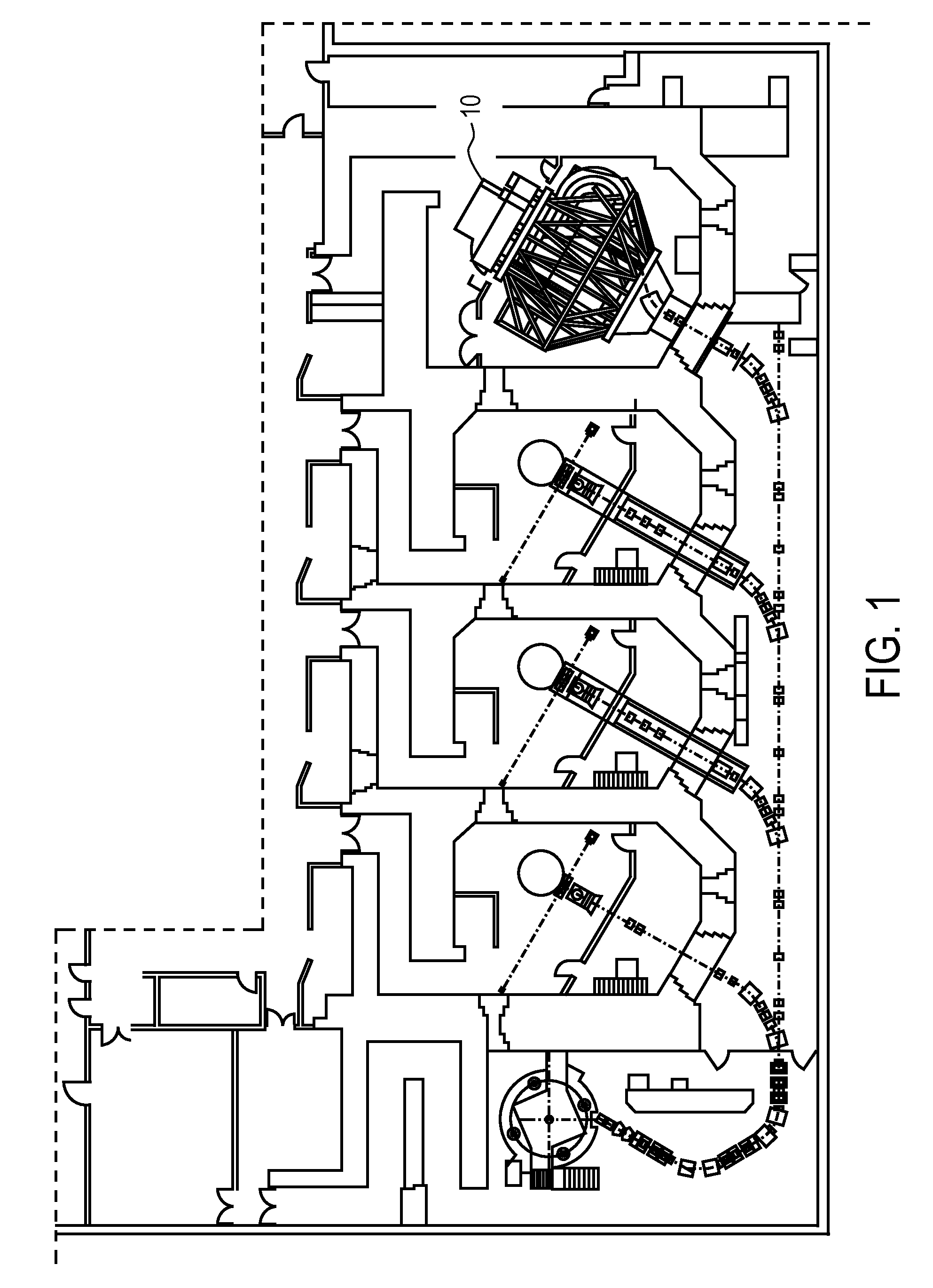
[0044]Through use of the superconducting magnet technology for beam delivery systems, it is proposed to reduce the capital cost of proton systems to be competitive with that of advanced x-ray systems on a per treatment fraction use basis. The compact isocentric gantry design for particle therapy presented herein is based upon innovative superconducting magnet systems.

[0045]Isocentric gantry systems described herein can include a number of superconducting magnets to reduce the overall size and swept volume of the gantry assembly. The coil windings of a superconducting magnet are typically made of wires or tapes of superconducting material. During operation, the magnet coils must be cooled below their critical temperature; the temperature at which the superconducting material changes from the normal resistive state and becomes a superconductor. Cryocoolers can be used to reach the temperature of about 5 degrees Kelvin required for most common superconducting material. There are two op...


PUM


Abstract

A gantry for administering proton beam therapy with improvements which reduce the size, weight, costs and radiation beam loss associated with proton beam therapy systems currently commercially available. The gantry utilizes achromatic superconducting multi-function electromagnet systems wherein the magnets can include dipoles and quadrupoles. The achromatic properties of the rampable magnet systems allow for ease of transmission of the beam whose energy is rapidly changed through a large range of different energies without changing of the strength of the magnetic fields or dipole settings. The magnets may be made with either low or high temperature superconductors. The gantry design further integrates beam scanning but keeps the gantry isocentric. A much greater fraction of the beam can be transmitted through the gantry than with current art, thereby reducing radiation shielding requirements and the demand put on the accelerator to produce large quantities of proton beam.

Description

CROSS REFERENCE TO RELATED APPLICATIONS[0001]This application claims the benefit under 35 U.S.C. 119 of U.S. Provisional Patent Application No. 61 / 257,329, filed Nov. 2, 2009, titled “Compact Isocentric Gantry”. This application is herein incorporated by reference in its entirety.INCORPORATION BY REFERENCE[0002]All publications, including patents and patent applications, mentioned in this specification are herein incorporated by reference in their entirety to the same extent as if each individual publication was specifically and individually indicated to be incorporated by reference.FIELD OF THE INVENTION[0003]The present invention generally relates to proton therapy. More specifically, the present invention relates to compact isocentric gantries for use in proton therapy centers.BACKGROUND OF THE INVENTION[0004]Over half of all patients in the US with cancer are treated with radiation therapy.[0005]Radiation therapy is based on irradiating the patient, more particularly his or her ...

Claims


Application Information

Patent Timeline
Patent Type & Authority Patents(United States)
IPC IPC(8): H05H13/00
CPCA61N5/10A61N5/1081A61N2005/1087A61N5/1043A61N5/1077
Inventor CAMERON, JOHN M.ANFEROV, VLADIMIRANTAYA, TIMOTHY A.
Owner PRONOVA SOLUTIONS
Why Eureka
Try Eureka