
Non-damaging slips and drillable bridge plug

a bridge plug and non-damaging technology, applied in the direction of fluid removal, sealing/packing, borehole/well accessories, etc., can solve the problems of stress cracking, permanent damage to the outside or inside surface of the tubular, stress failure of the tubular, etc., and achieve the effect of convenient drillability

Active Publication Date: 2013-11-12
INNOVEX DOWNHOLE SOLUTIONS INC
View PDF24 Cites 50 Cited by
  • Summary
  • Abstract
  • Description
  • Claims
  • Application Information

AI Technical Summary

Benefits of technology

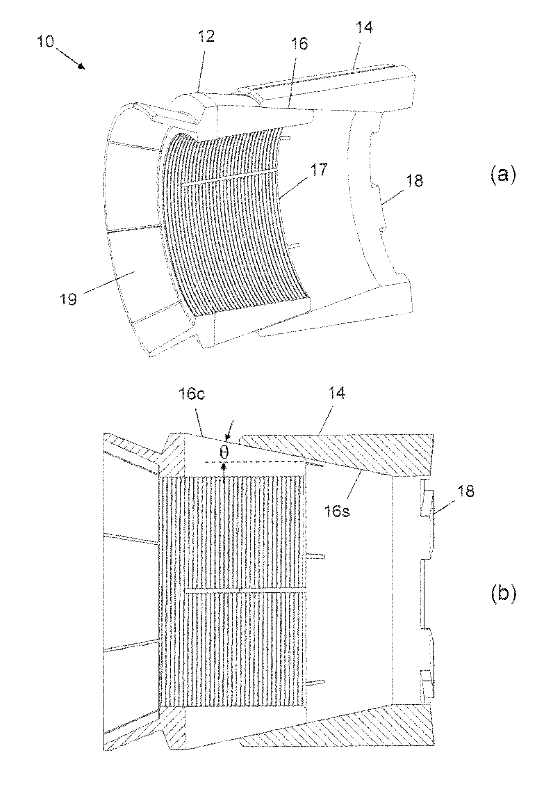
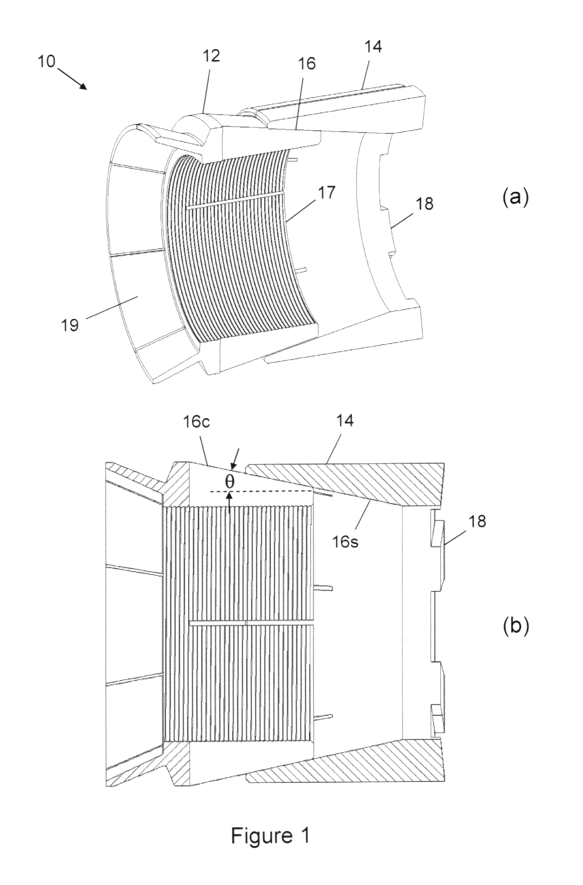
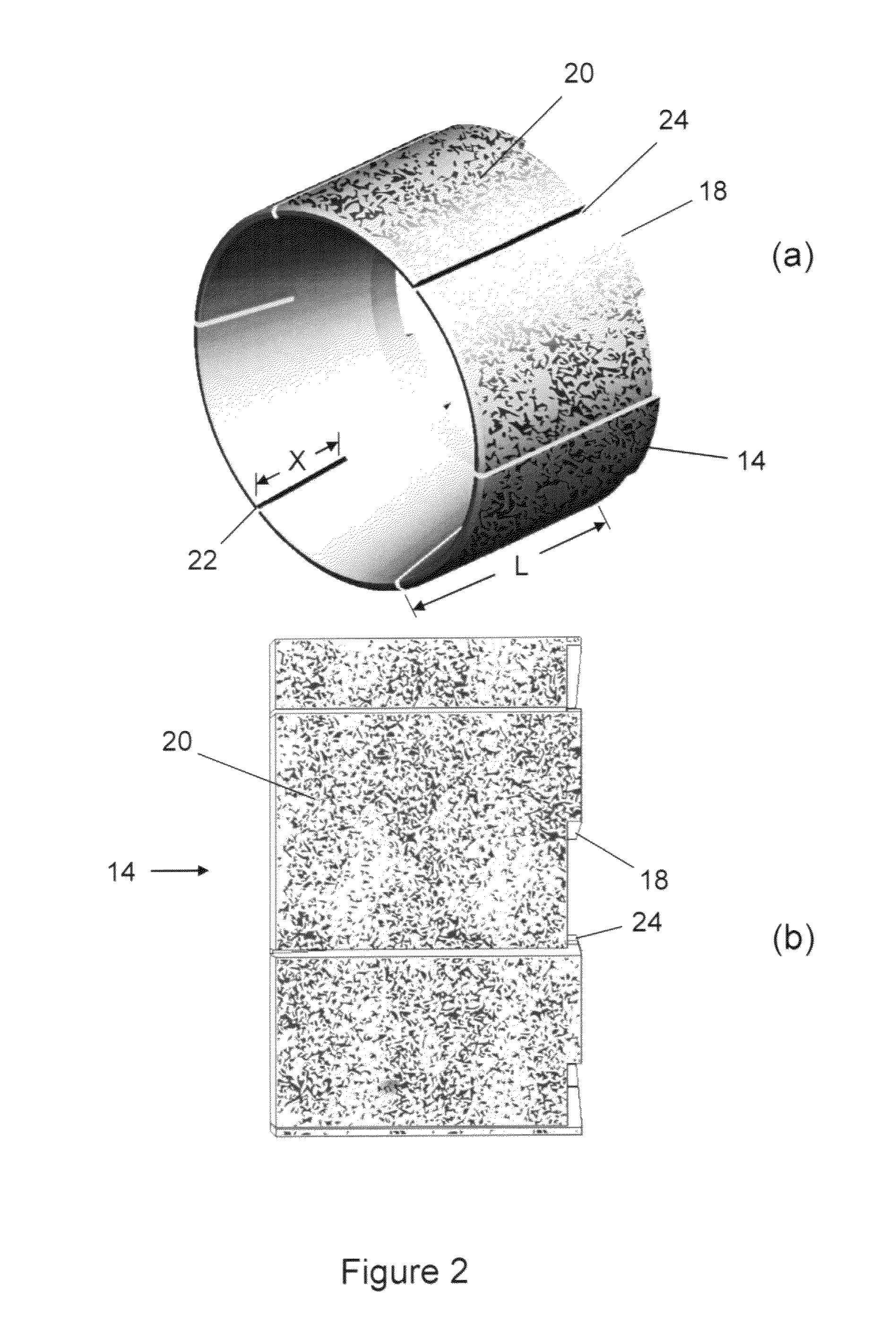
[0009]A slip assembly that can be used to anchor tools or devices at a selected location in a tubular is provided. The slip assembly consists of slips and a cone adapted for moving the slips out radially when the cone moves along slidable surfaces beneath the slips, the slidable surfaces having a selected angle from the axis of movement. The cone and slips are preferably made of easily drillable, ductile material, such as an aluminum alloy. The smooth outside surface of the slips is coated with grit and the slips may include slits and grooves to allow the slips to break into multiple segments during setting. The cone has slits that are narrowed during setting to cause threads inside the cone to become engaged with threads on the mandrel so as to prevent rotation of the cone with respect to a mandrel supporting the slip assembly.

Problems solved by technology

The embedment of the hardened steel teeth of slips causes permanent damage to the outside or inside surface of tubulars.
Under some conditions the damage is inconsequential, but under other conditions, such as when high-strength or corrosion-resistant pipe is used, the damage may lead to stress cracking or stress failure of the tubular.
Some bridge plugs are not retrievable because the slips are not designed to release and retract but to be removed by milling or drilling.
In prior art bridge plugs, it has been found that lower components of the bridge plug may no longer engage the mandrel during drilling or milling of the plug, allowing them to spin or rotate within the casing and greatly increase the time required for drilling.

Method used


Image

  • Non-damaging slips and drillable bridge plug
  • Non-damaging slips and drillable bridge plug
  • Non-damaging slips and drillable bridge plug

Examples


example 1

[0026]A bridge plug was constructed according to FIG. 4 and the accompanying description. The material of construction for all parts (except the elastomer and the coating on the slips) was an aluminum alloy. The coating was a mix of crushed tungsten carbide 50 mesh particles and nickel alloy powder from Tunco Manufacturing Co. of Flowery Branch, Ga. The coating was sprayed on the surface of the slips using a thermal spray application (plasma).

[0027]The bridge plug was tested as per API 11D1. The plug length at assembly was 16.7 inches. The plug with running tool was placed inside a joint of 5½-in casing in an oil bath and the temperature increased to a designated operating temperature of 300 degrees Fahrenheit. The tool was set with a hydraulic setting tool and the setting tool was then removed. The inner mandrel separated at the notch, making the plug assembly approximately 13.6 inches long. A cap was applied to the fixture and pressure above the plug was increased to 10,000 psi an...

example 2

[0030]A frac plug was constructed according to FIG. 4. The material of construction was the same as the bridge plug. The ball was made of an aluminum alloy.

[0031]The frac plug length before setting was 16.7 inches. The frac plug with running tool was placed inside a joint of casing in an oil bath and the temperature increased to a designated operating temperature of 300 degrees Fahrenheit. The tool was then set with a hydraulic setting tool and the setting tool was then removed. The mandrel separated at the notch, making the plug assembly approximately 13.6 inches long. A ball was dropped into the fixture and a cap was applied. Pressure above the plug was increased to 10,000 psi and held for 15 minutes. There was no leakage of fluid past the plug. Pressure above the plug was then cycled several times between ambient and 10,000 psi. Each time there was no leakage of fluid past the plug. This process was repeated for 12,500 psi and 15,000 psi and held for 15 minutes each time. Again t...


PUM


Abstract

A non-damaging slip assembly includes slips having grit on a smooth surface, the slips preferably made from a ductile material, such that the slips do not cause damage to the wall of a tubular when the slips are set. The slips fail under tensile force during setting. The cone used to expand the slips may have slits that narrow during setting of the slips. The slip assembly may be used to anchor a variety or devices inside a tubular. A drillable, non-damaging bridge plug using the non-damaging slip assembly has a threaded mandrel holding the cone by threads inside the cone. When the slips are set, the slits in the cone narrow such that threads in the cone do not allow rotation of the slips as they are drilled. The bridge plug can be drilled by a PDC bit without damaging the tubular.

Description

BACKGROUND OF INVENTION[0001]1. Field of the Invention[0002]This invention relates to a slip assembly that can be used to press against the inside wall of a tubular to anchor a tool in the tubular without significantly deforming or damaging the wall, even at high anchoring force, and the use of the slip assembly in a bridge plug or other device to be anchored in a tubular.[0003]2. Description of Related Art[0004]Slips are any self-gripping device consisting of three or more wedges that are held together and form a near circle either (1) around an object to be supported by contact with surfaces of the slips or (2) within a tubular to anchor an object within the tubular. The first type of slips is normally used to grip a drill string, wire line or other cylindrical devices suspended in a well. The second type of slips is used to anchor bridge plugs, frac plugs, cement retainers and other devices temporarily or permanently placed at a selected location within tubulars. Normally, the sl...

Claims


Application Information

Patent Timeline
Patent Type & Authority Patents(United States)
IPC IPC(8): E21B23/00
CPCE21B33/129E21B33/134
Inventor MAILAND, JASON C.BAHR, GLENN A.
Owner INNOVEX DOWNHOLE SOLUTIONS INC
Learn More