Method and system for purging moisture from an oxygenator

a technology of oxygenator and moisture, applied in the field of extracorporeal systems, can solve the problems of high negative pressure in the moisture collecting unit itself, and achieve the effect of improving the gas exchange properties

Active Publication Date: 2013-11-19
ALUNG TECH INC
View PDF34 Cites 2 Cited by
  • Summary
  • Abstract
  • Description
  • Claims
  • Application Information

AI Technical Summary

Benefits of technology

[0009]The present invention is directed to a method and system for improving the gas exchange properties of oxygenators which utilize hollow fiber membranes for removing carbon dioxide and / or adding oxygen to a patient's blood via extracorporeal circulation. The present invention improves the gas exchange properties by intermittently removing moisture buildup from the fibers of the oxygenator. The present invention utilizes negative pressure, or a vacuum, to draw the sweep gas into the oxygenator and a moisture purging system which intermittently removes any moisture from the oxygenator. The present invention accomplishes this without the need to increase the pressure of the sweep gas as it enters the fiber bundle of the oxygenator. The moisture purging system of the present invention generates the “cough” that removes moisture from the oxygenator without the need to increase the pressure of the sweep gas entering the oxygenator. Accordingly, there is no increased risk of forming gas emboli in the blood flowing through the oxygenator since the sweep gas is being drawn into, rather than being forced or driven into the oxygenator. This removal of accumulated moisture from the oxygenator can be performed intermittently to insure that there is little possibility of any appreciable moisture accumulating in the fibers for a prolonged period. As a result, the gas exchange rate for the oxygenator should not be affected by moisture accumulation in the oxygenator during usage.
[0010]The present invention utilizes a source which will draw the sweep gas into the oxygenator utilizing a vacuum (negative pressure). In one aspect of the present invention, a vacuum pump, for example, could be used to draw the sweep gas into the oxygenator, rather than positively pushing sweep gas into the oxygenator. The vacuum source would be connected to the sweep gas exit port of the oxygenator to draw, rather than drive, the sweep gas through the fiber bundles. As a result of utilizing a vacuum to draw the sweep gas into the oxygenator, rather than using a positive pressure source which pushes or drives the sweep gas into the inlet port of the oxygenator, there is little chance of the sweep gas permeating the fiber membrane into the blood flowing through the oxygenator. Therefore, there is little chance of gas emboli being formed in the blood being returned to the patient during the moisture purging steps described below. In one aspect of the invention, a source for the sweep gas (usually oxygen or air) would be connected to the gas inlet port of the oxygenator. The moisture purging system of the present invention would be connected to the sweep gas outlet of the oxygenator and will create a build up of negative pressure that, when released, will cause a sudden rush of sweep gas though the oxygenator, effectively removing all accumulated moisture.
[0012]The moisture purging system further includes a flow control mechanism associated with the moisture collecting unit and the oxygenator. In one aspect of the present invention, the flow control mechanism can be a simple pinch valve which opens and closes the conduit (for example, flexible tubing) connecting the moisture collecting unit to the oxygenator. When the flow control mechanism is placed in the open position, the sweep gas will freely flow through the conduit connecting the oxygenator to the moisture collecting unit as it is being drawn by the vacuum source. When the flow control mechanism is placed in the closed position, fluid communication between the moisture collecting unit and the oxygenator will be temporarily closed. The flow of sweep gas through the oxygenator also will be temporarily stopped. The vacuum source, however, will continue to evacuate any sweep gas contained within the moisture collecting unit, which causes a build up of high negative pressure within the moisture collecting unit itself. After a short duration, the flow control mechanism will be placed back into the open position. When this occurs, sweep gas is again drawn into, and rushes through, the fibers of oxygenator at a high velocity to fill the vacuum created in the moisture collecting unit. The velocity of the sweep gas flow will increase with higher vacuum achieved in the moisture collecting unit. This increase in the velocity of the sweep gas will cause any moisture accumulating in the fibers of the oxygenator to be removed and drawn into the moisture collecting unit with the sweep gas. As the vacuum developed in the moisture collecting unit increases, better moisture purging will take place. As a result, the fibers of the oxygenator can be maintained clear of moisture accumulation during usage.
[0013]The flow control mechanism can be connected to a signal source designed to open and close the fluid path between the oxygenator and the moisture collecting unit. The period that the mechanism remains open or closed could be easily programmed into the signal source to activate the moisture purging system. Since it usually takes a bit of time to accumulate moisture in the fibers of the oxygenator, the moisture purging system will usually remain in the open position in which sweep gas is being continually drawn through the oxygenator. The signal source could then provide a signal to the flow control mechanism to assume the closed position, and will dictate the duration that the flow control mechanism will remain in the closed position. After that period is reached, the signal source will move the flow control mechanism back to the open position to purge the moisture from the oxygenator. Again, the duration that the flow control mechanism remains in the open or closed system can be determined and easily adjusted using controls associated with the signal source. The described system is therefore capable of removing moisture from the oxygenator without increasing the pressure within the fibers of the oxygenator and without compromising patient safety.
[0014]The moisture purging system of the present invention can be used on a number of different oxygenators which utilize hollow fiber membranes for removing carbon dioxide or adding oxygen to a patient's blood via extracorporeal circulation. The present invention can be utilized with a number of different systems which supply the necessary sweep gas to the oxygenator. Likewise, the moisture purging system of the present invention can be connected with additional instrumentation which can, for example, analyze the oxygen / carbon dioxide content of the sweep gas as it exits the oxygenator. Feedback loop controls could be associated with such equipment and the signal source to adjust the timing of the intervals when the flow control mechanism is placed in either the open or closed position.

Problems solved by technology

The vacuum source, however, will continue to evacuate any sweep gas contained within the moisture collecting unit, which causes a build up of high negative pressure within the moisture collecting unit itself.

Method used


Image

  • Method and system for purging moisture from an oxygenator
  • Method and system for purging moisture from an oxygenator
  • Method and system for purging moisture from an oxygenator

Examples


Embodiment Construction

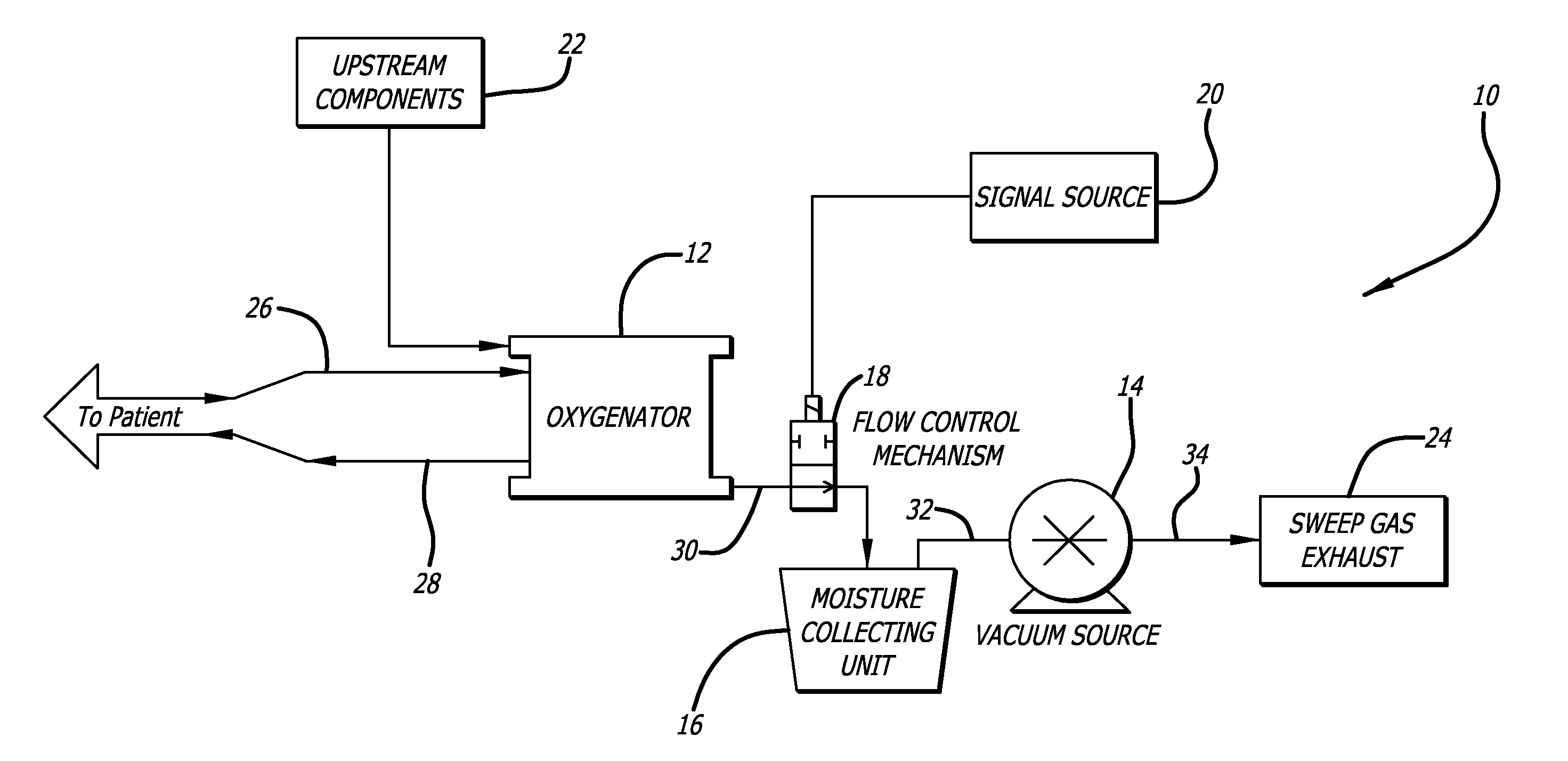
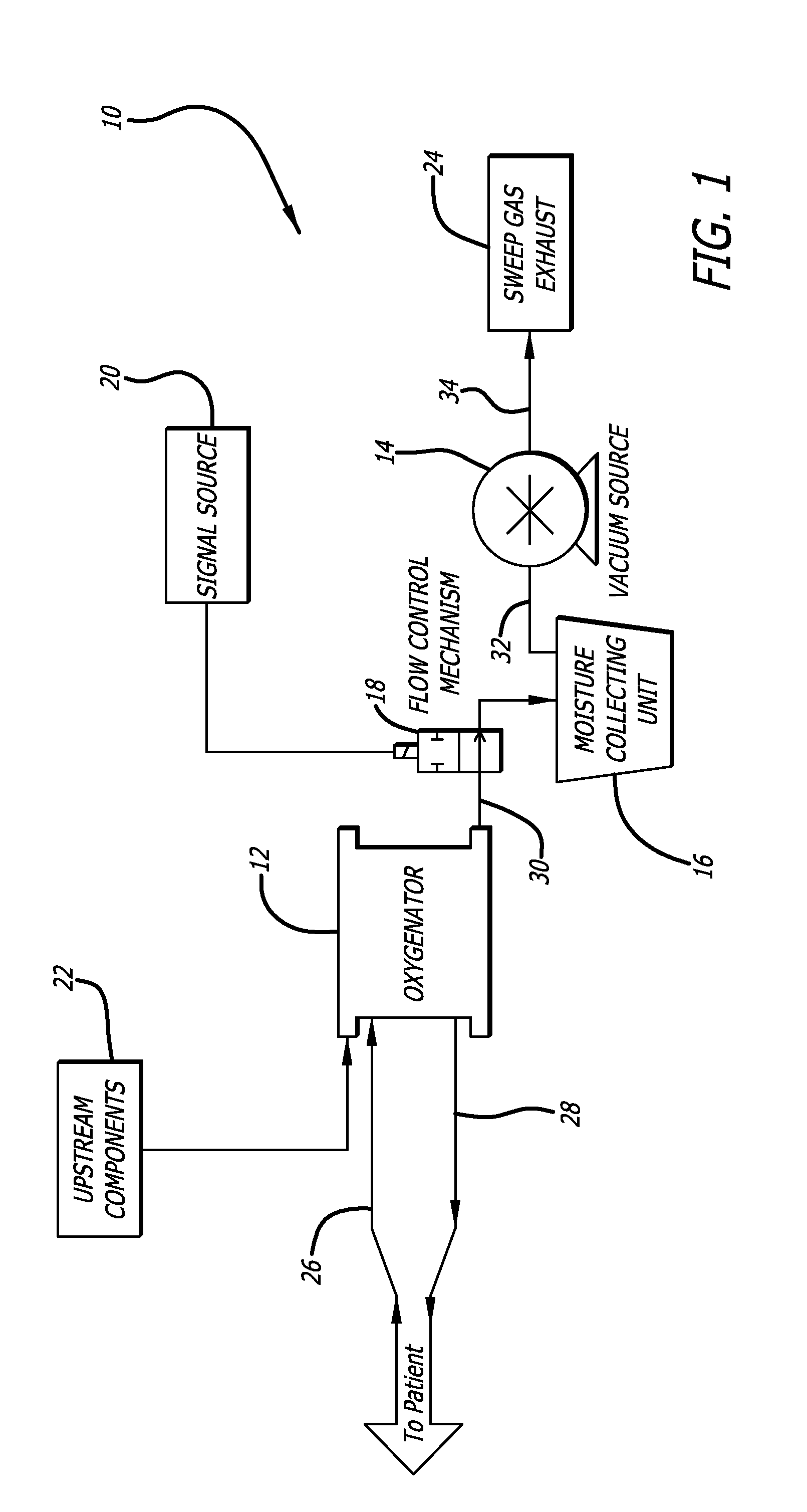
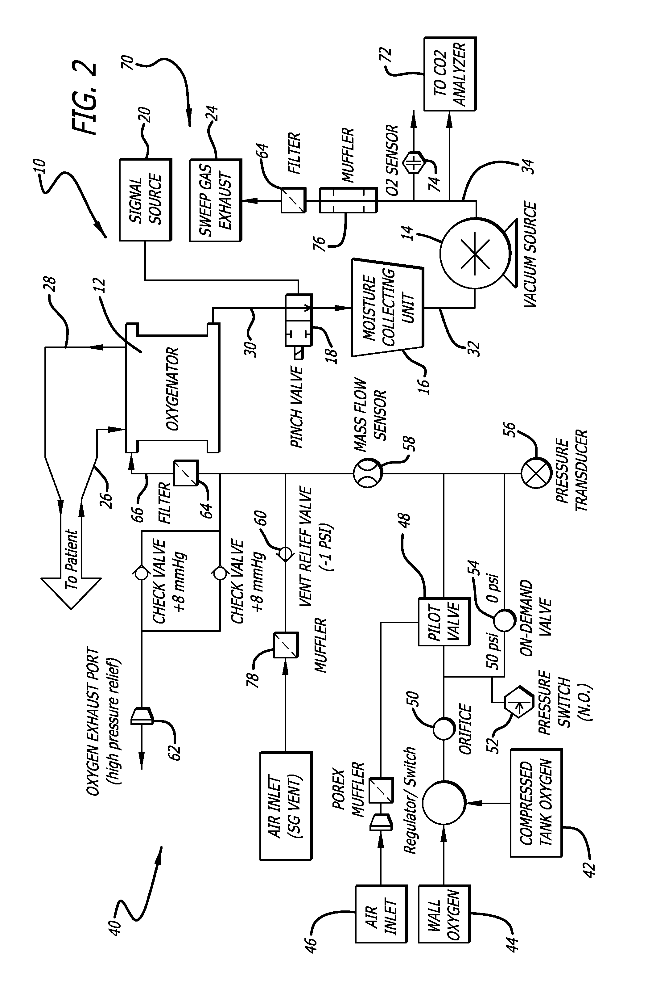
[0018]Referring now to FIG. 1, a block diagram depicting the moisture purging system 10 is shown. The moisture purging system 10 is utilized to remove accumulated moisture from an oxygenator 12 which utilizes hollow fiber membranes for removing carbon dioxide and / or adding oxygen to a patient's blood via extracorporeal circulation. The moisture purging system 10 includes a vacuum source 14, shown in FIG. 1 as a vacuum pump, which is in communication with the sweep gas exit port of the oxygenator. The moisture purging system 10 further includes a moisture collecting unit 16 which, in FIG. 1, is shown as a moisture canister or water trap which is a well known device utilized in medical and other systems for collecting unwanted moisture from a system. Lastly, the moisture purging system 10 includes a flow control mechanism 18 shown as a pinch valve in FIG. 1. It would be appreciated by those skilled in the art that this flow control mechanism can be any one of a number of different mec...


PUM


Abstract

A method and system for improving gas exchange properties of oxygenators which utilize hollow fiber membranes for removing carbon dioxide or adding oxygen to a patient's blood via extracorporeal circulation by removing moisture accumulating in the fibers are disclosed. The system utilizes a vacuum source for drawing sweep gas into the oxygenator, a moisture collection unit for storing moisture removed from the oxygenator, the moisture collecting unit being in communication with the oxygenator and the vacuum source and a flow control mechanism having an open position which allows sweep gas exiting the oxygenator to flow to the moisture collecting unit and a closed position which stops the flow of sweep gas from the oxygenator to the moisture collecting unit. The vacuum source draws sweep gas through the oxygenator and moisture collecting unit when the flow control mechanism is in the open position and the vacuum source creates a vacuum buildup in the moisture collecting unit when the flow control mechanism is in the closed position. The vacuum in the moisture collecting unit provides a sudden increase to the flow rate of the sweep gas to draw moisture with the sweep gas exiting the oxygenator when the flow control mechanism is returned to the open position.

Description

FEDERALLY SPONSORED RESEARCH[0001]This invention was not a result of federally sponsored research.CROSS-REFERENCES TO RELATED APPLICATIONS[0002]This application claims no priority to any prior application.BACKGROUND OF THE INVENTION[0003]The present invention relates generally to extracorporeal systems for oxygenating and pumping blood during, for example, cardiac surgery. More specifically, the present invention relates to a method and system for improving gas exchange properties of oxygenators which utilize hollow fiber membranes for removing carbon dioxide and / or adding oxygen to a patient's blood via extracorporeal circulation.[0004]It has been reported that 350,000 Americans die of lung disease each year, most from Acute Respiratory Distress Syndrome (ARDS) and Chronic Obstructive Pulmonary Disease (COPD). The most common treatment is mechanical ventilation, but may further exacerbate respiratory insufficiency and can cause serious side effects, such as barotrauma and volutraum...

Claims


Application Information

Patent Timeline
Patent Type & Authority Patents(United States)
IPC IPC(8): A61M1/00
CPCA61M1/1698B01D63/02B01D63/16B01D65/02A61M1/1006A61M1/265A61M1/267B01D2311/13B01D2321/02B01D2313/18B01D2313/243B01D2313/50B01D2313/90Y10T137/86067Y10T137/0396
Inventor MORLEY, SCOTT W.BIENIEK, PAULROSENBERG, MEIR
Owner ALUNG TECH INC
Why Eureka
Try Eureka