Power storage device
a power storage device and power technology, applied in the field of power storage devices, can solve problems such as unexpected potential, and achieve the effect of high discharge voltage and high energy density
- Summary
- Abstract
- Description
- Claims
- Application Information
AI Technical Summary
Benefits of technology
Problems solved by technology
Method used
Image
Examples
embodiment 1
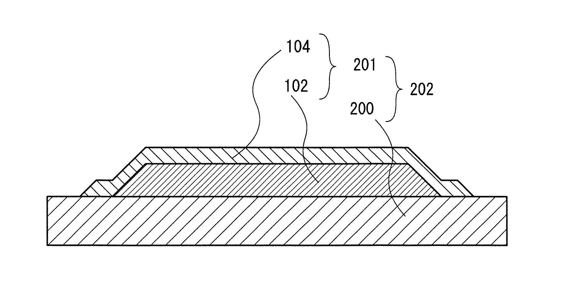
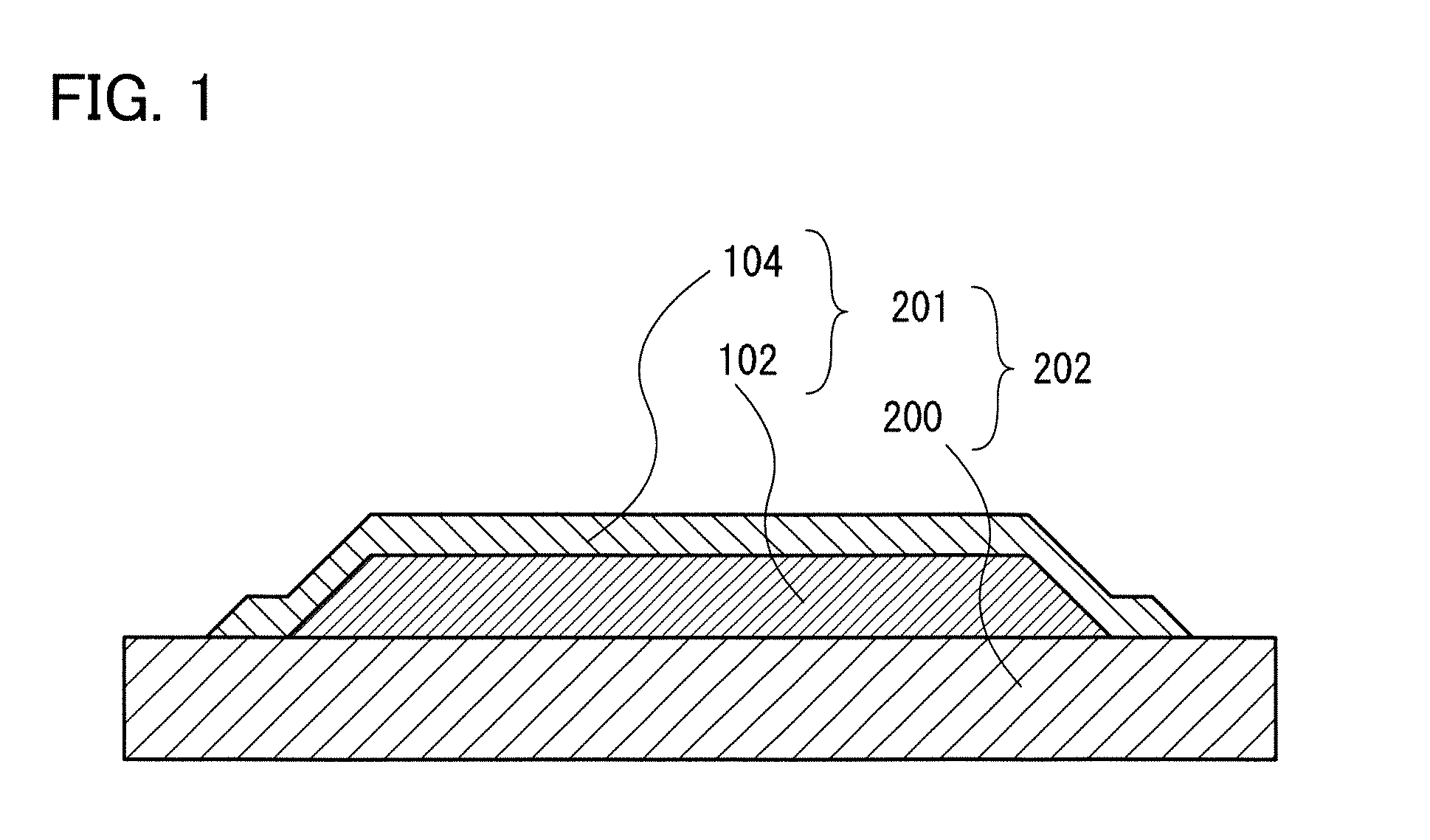
[0043]In this embodiment, a structure of a positive electrode included in a power storage device according to one embodiment of the present invention will be described with reference to FIG. 1.
[0044]FIG. 1 is a schematic cross-sectional view of a positive electrode included in a power storage device which is one embodiment of the present invention.
[0045]As illustrated in FIG. 1, in this embodiment, a positive electrode active material layer 201 includes a film-form first region which includes a compound containing lithium and nickel (hereinafter, this region is referred to as a first region 102); and a film-form second region which includes a compound containing lithium and one or more of iron, manganese, and cobalt, but not containing nickel (hereinafter, this region is referred to as a second region 104). The first region 102 is covered with the second region 104.
[0046]That is, a top surface and a side surface of the film-form first region 102 which includes the compound containin...
embodiment 2
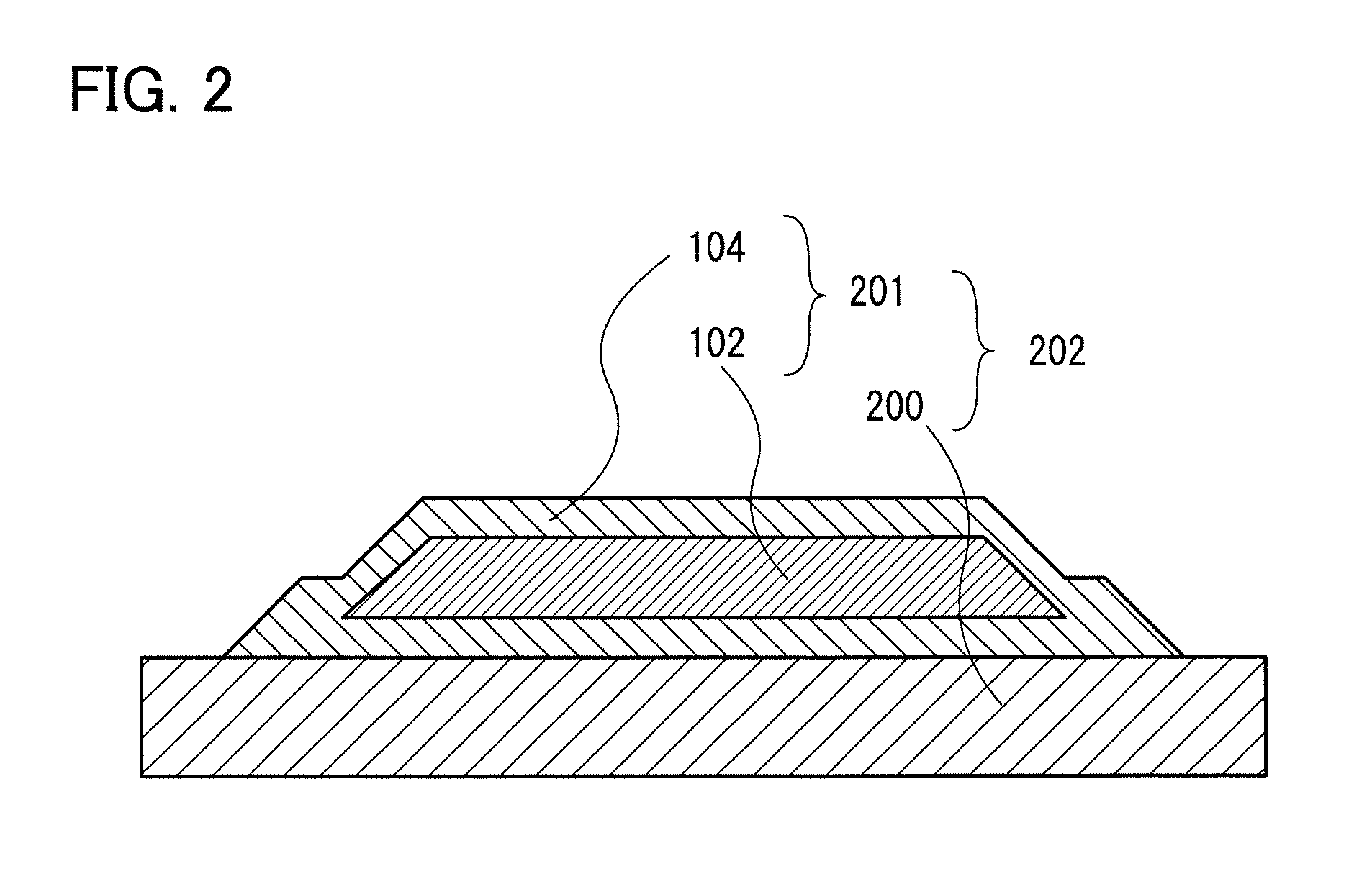
[0060]In this embodiment, a structure of a positive electrode included in a power storage device according to one embodiment of the present invention, which is a different example from the example illustrated in FIG. 1, will be described with reference to FIG. 2, FIG. 3, and FIG. 4.
[0061]FIG. 2, FIG. 3, and FIG. 4 are each a schematic cross-sectional view of a positive electrode included in a power storage device which is one embodiment of the present invention.
[0062]As illustrated in FIG. 2, in this embodiment, the positive electrode active material layer 201 includes the film-form first region 102 which includes a compound containing lithium and nickel; and the film-form second region 104 which includes a compound containing lithium and one or more of iron, manganese, and cobalt, but not containing nickel. The first region 102 is covered with the second region 104. A top surface and a side surface of the first region 102 are covered with the second region 104. In addition, the sec...
embodiment 3
[0065]In this embodiment, a method for forming a positive electrode included in a power storage device which is one embodiment of the present invention will be described below.
[0066]First, the positive electrode current collector 200 is prepared (FIG. 5A).
[0067]There is no particular limitation on a material used for the positive electrode current collector 200; however, a material having high conductivity such as platinum, aluminum, copper, or titanium can be used. In this embodiment, titanium is used.
[0068]Next, over the positive electrode current collector 200, the first region 102 is formed using a compound containing lithium and nickel (FIG. 5B).
[0069]As a method for forming the first region 102 including the compound containing lithium and nickel, a dry process such as a PVD method (e.g., a sputtering method), a vacuum evaporation method, or a CVD method (e.g., a plasma CVD method, a thermal CVD method, or an LPCVD method) can be used. By forming the first region 102 including...
PUM
| Property | Measurement | Unit |
|---|---|---|
| thickness | aaaaa | aaaaa |
| temperature | aaaaa | aaaaa |
| thickness | aaaaa | aaaaa |
Abstract
Description
Claims
Application Information
 - R&D
- Intellectual Property
- Life Sciences
- Materials
- Tech Scout
- Unparalleled Data Quality
- Higher Quality Content
- 60% Fewer Hallucinations
Browse by: Latest US Patents, China's latest patents, Technical Efficacy Thesaurus, Application Domain, Technology Topic, Popular Technical Reports.
© 2025 PatSnap. All rights reserved.Legal|Privacy policy|Modern Slavery Act Transparency Statement|Sitemap|About US| Contact US: help@patsnap.com


